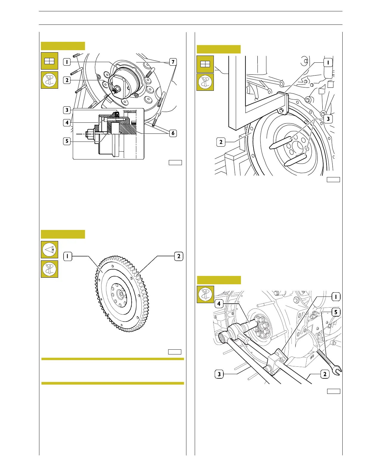
Figure 42
Figure 43
- Apply tool 99368511 part (6) to the rear output shaft
tang (5), secure it with screws (4) and fit the new sealin g
ring (3).
Position part (1) on part (5), screw nut (2) until
completing sealing ring (3) fitting into flyw heel housin g
(7).
ENGINE FLYWHEEL
00901t
75696
NOTE
Check the important measurements depending on
the application.
- Check the condition of the teeth for the ring gear (2).
If the teeth are broken or very worn, remove it from the
engine flywheel (1) using an ordinary drift and fit the new
ring gear, heated previously to a temperature of 150˚C
for 15’ P 20’; the bevel on the inner diameter of the ring
gear should be facing the engine flywheel.
Figure 44
- Screw the pins 99367019 (3) onto t he crankshaft and fit
the flywheel (2) with tool 99368533 (1) and a suita ble
lift.
Fitting the engine flywheel
83436
Figure 45
- Stop engine shaft rotation with tool 99368502: the fixed
wrench (5) keeps the flywheel in position preventing its
rotatio n. Assemble tool 99368546 (1) and tigh ten the
fixing sc rews that were previously lubricated with
”UTDM” oil up to the prescribed torque by using torque
multiplier 99389816 (2), dynamometric wrenc h
99389818 (3) and bush wrench 99367016 (4); for
angular closu re use tool 99395216 (2).
103216
Fitting the rear oil seal
SECTION 3 - INDUSTRIAL APPLICATION
23
VECTOR 8 ENGINES
Print P2D32V001E Base - April 2006
 Loading...
