Figure 95
Figure 96
Figure 97
Figure 98
Figure 99
Figure 100
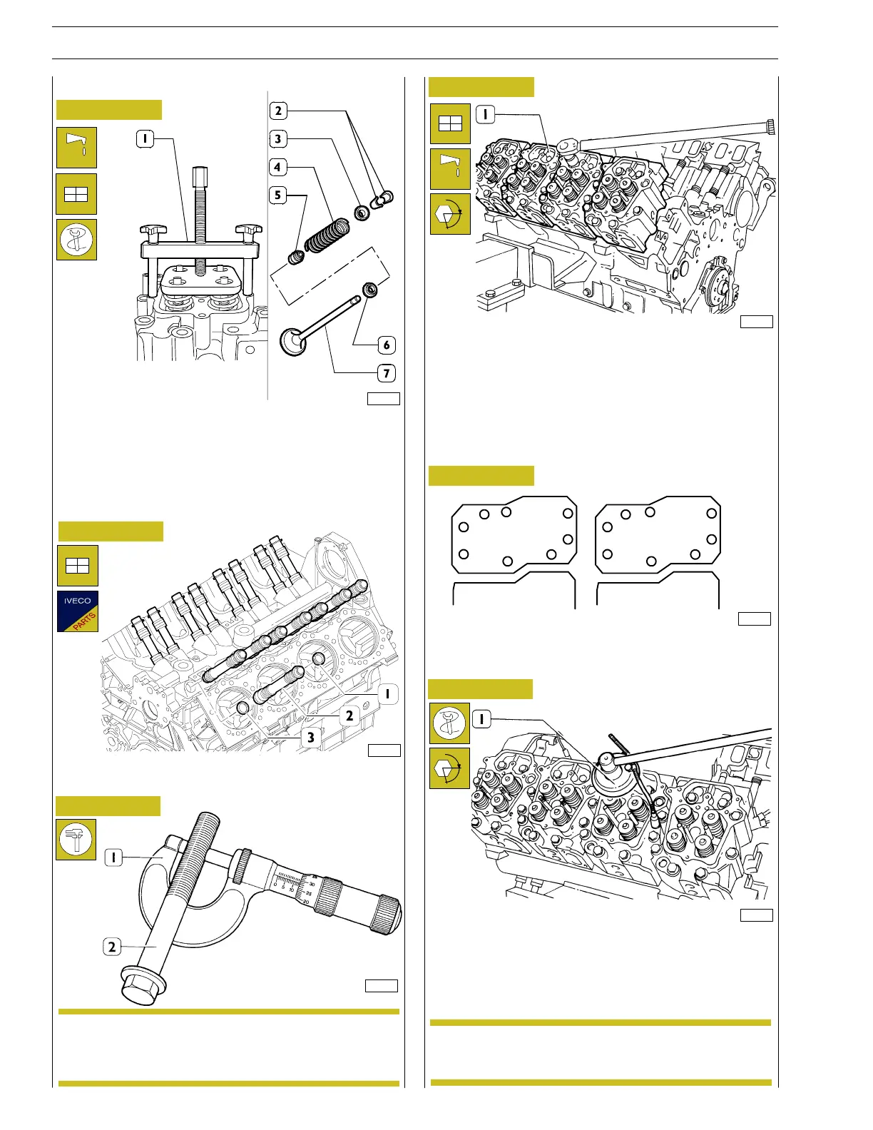
Fitting the valves
- Lubricate the stems of the valves (7) and insert them in
their respective valve guides. Position the bottom plates
(6), springs (4) and top plates (3) on the cylinder head.
Using tool 99368544 (1), compress the springs and fit the
retaining cotters (2).
- Fit the rings (1 and 3) on the cases (2) and insert them in
the cylinder block.
Installing the cylinder head
To reuse the bolts ( 2) fixing the cylinder heads, check
with a micrometer (1) that the diameter of its thread
is no less than 14.5 mm.
4
7
8
1
3
5
6
2
3
5
6
2
4
7
8
1
α
Fit new cylinder head gaskets. Mount the cylinder heads (1).
Lubricate the fixing bolts with ”UTDM” oil. Align the cylinder
heads with the tool applied in the holes to fasten the exhaust
manifolds.
Tighten the cylinder head bolts, following the order shown i n
the following figure, as follows:
- first phase: pre—torque 70 Nm;
DIAGRAM OF TIGHTENING SEQUENCE FOR
CYLINDER HEAD BOLTS
α
Apply tool 99395216 (1) to the wrench.
- second phase: angle 240°;
- guard torque: 220 — 390 Nm.
The screw can be used again as long as the external
diameter of the shank is 14. 5 mm long in each point.
103214
37724
24546
82719
36618
37725
NOTE
NOTE
38
SECTION 4 - OVERHAUL AND TECHNICAL SPECIFICATIONS
VECTOR 8 ENGINES
Base - April 2006 Print P2D32V001E
 Loading...
