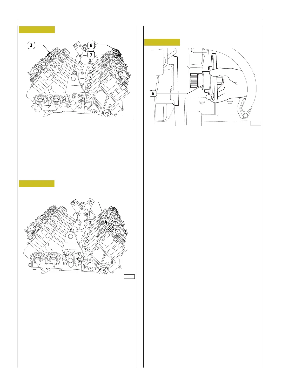
Figure 57
Adjusting operating clearance between valves
and rockers
- Undo the three nuts fixing the flywheel cover casing
cover (side opposite the starter motor). Fit tool
99368502 (6) with pinion 99368547 to rotate the engine
flywheel and secure it using the nuts for the cover
removed.
- After fitting the 24 mm ratchet wrench on the back of
tool 99368502, turn the engine flywheel until we obtain
the required cylinder balanc i ng (the 4 valves are at the
same height).
Figure 58
- Unscrew the three fixing nuts of the cover of the box
that covers the flywheel (on the opposite side of the
starting mot or). Insert tool 99368502 in order to turn
the engine flywh eel an d fix it with the nu t s of th e cover
that has been removed.
- Turntheengineclockwisefor360˚, th en assemble
rocker—arm unit s 3-7 e 8.
- Check that the contact between the register and the
plate is centred and that the rods can turn freely.
Figure 59
- Apply the 20 ÷ 120 Nm torque wrench with the 1/2”
square connect ion to the wrench 99389813 to lock
bolts M12x1,75 to a torque of 80 ÷ 89 Nm.
- After the rocker—arm control rods (1) have been
assembled check that they are properly inserted in the
tappet seats and then lubricate then with engine oil in the
area in which the rod slides.
89827
81603
89829
28
SECTION 3 - INDUSTRIAL APPLICATION
VECTOR 8 ENGINES
Base - April 2006 Print P2D32V001E
 Loading...
