Figure 3
Figure 4
- Once engine is disassembled, clean accurately the
cylinder—block assembly. Use the proper rings to handle
the cylinder unit. The engine block shall not show cracks.
- Check operating plug conditions and replace them in case
of uncertain seal or if rusted.
- Inspect cylinder barrel surfaces; they shall be free from
seizing, scores, ovalisation, taper or excessive wear.
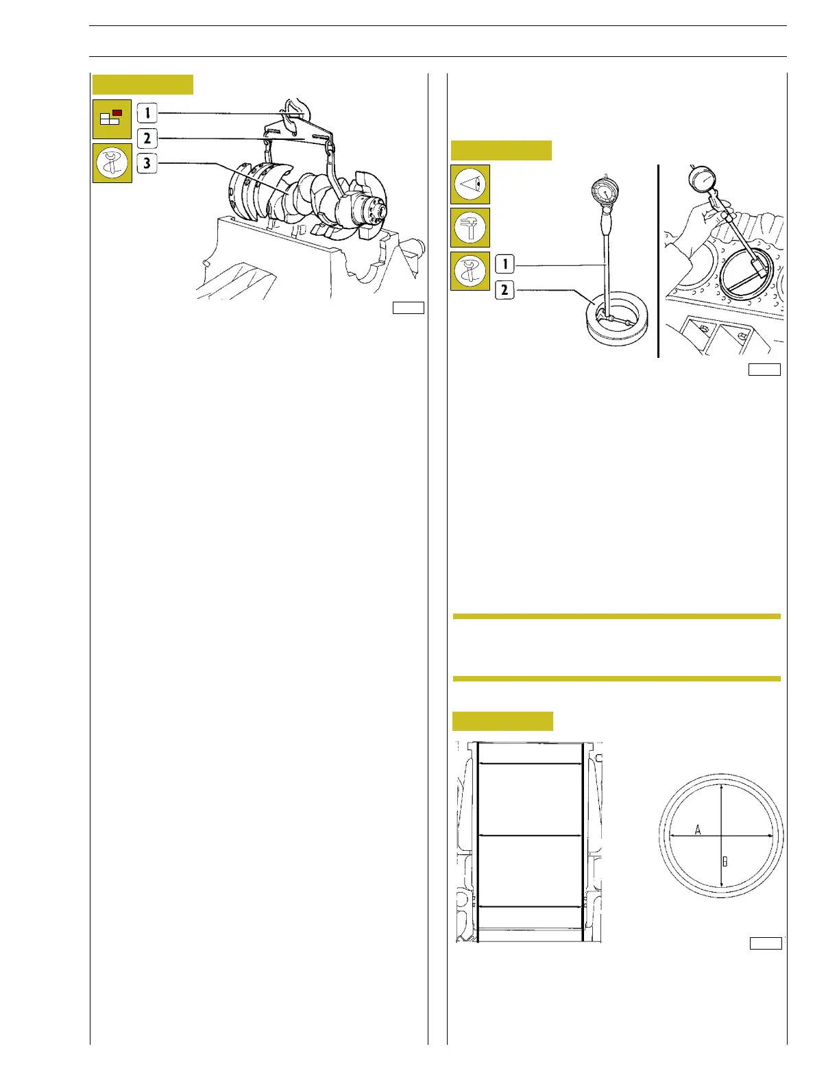
Inspection of cylinder barrel bore to check ovalisation,
taper and wear shall be performed using the bore dial
gauge 99395687 (1) fitted with the dial gauge previously
set to zero on the ring gauge (2) of the cylinder barrel
diameter.
Figure 5
REPAIR OPERATIONS
CYLINDER UNIT
Checks and measurements
Should the ring gauge be not available, use a
micrometer for zero—setting.
- Measurements shall be performed on each cylinder, at
three different heights in the barrel and on two planes
perpendicular with each other: one parallel to the
longitudinal axis of the engine (A), and the other
perpendicular (B). Maximum wear is usually found on plane
(B) in c orrespondence with the first measurement.
- Using a hoist (1) and tool 99360500 (2), appropriately
fitted on the crankpins, extract the crankshaft (3) from the
cylinder assembly.
- Extract the camshaft from the cylinder assembly, taking
care not to damage the supporting bushings. Extract the
roller tappets.
1
2
3
16788
16792
NOTE
2284
SECTION 4 - OVERHAUL AND TECHNICAL SPECIFICATIONS 11
VECTOR 8 ENGINES
Print P2D32V001E Base - April 2006
 Loading...
