Figure 24
Figure 25
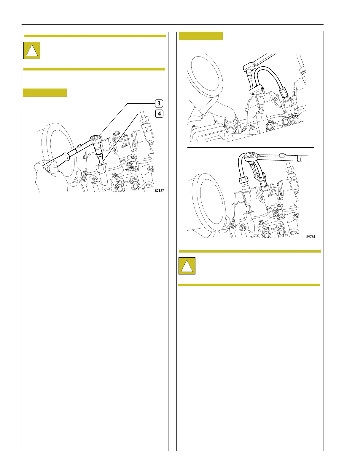
- Tight with a pre- torque of 20 Nm the fitting on both side,
flow-limiter and injector side. Durin g the tightenin g
procedure the injec t or and the flow-limiter have to be
hold against th e tighten direction.
- Tight with a final torque of 80±5 Nm the fitting on both
side, flow-limiter and injector side. During the t ightening
procedure the injec t or and the flow-limiter have to be
hold against th e tighten direction.
- Test engine for leak detection.
- Using the specific wrench, screw the cheese—headed
screw M10x70 back on to a tightenin g torque of 32 ÷ 36
Nm.
!
Always chan ge the O—ring in t he assembly phase.
Lubricate the O—ring before installation (u se
vaseline).
- Check the sealing surface of the leaking pipe and the
surface on the injector and flow limiter. Cleaning t he
surfaces and remove dirt i f necessary. In case the sealing
surface are damaged , replace the part.
- Lubricate with clean en gine oil the fitting and the sealing
surface.
- Tight by han d t he fitting on both side , flow-limiter an d
injector side.
!
During position ing please clean well the spherical
surfaces and the Threaded part of pipe by dipping it
in a clean contain er filled with clean motor oil.
94
SECTION 3 - INDUSTRIAL APPLICATION
VECTOR 8 ENGINES
Base - April 2006 Print P2D32V001E
 Loading...
