Figure 14
The pumping element (5) is oriented on the cam on the pump shaft.
In the suction phase, the pumping element is fed through the supply line (3). The amount of fuel to send to the pumping element
is decided by the pressure regulator (7).
Depending on the command received from the control unit, the pressure regulator will control the flow of fuel to the pumping
element. During the compression phase of the pumping element, the fuel pressure opens the common rail delivery valve (2),
before going out the outlet (1).
The pump shaft supports are lubricated through the ducts (oil channels) (8).
The pressure regulator (7) decides the amount of fuel with which to supply the pumping elements; any excess fuel flows out
through the duct (9).
The pressure relief valve (10), has the function of keeping a constant inlet pressure at 5 bar for the pressure regulator.
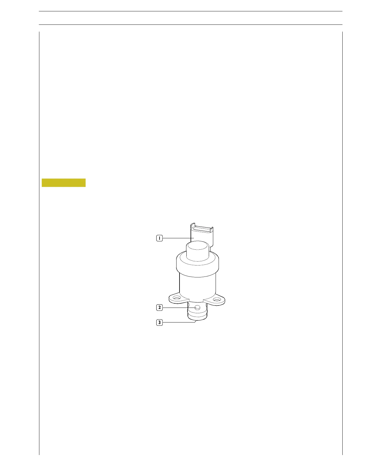
High pressure regulator
Located at the high—pressure pump inlet, on the low—pressure system, it controls the flow of fuel to th e h igh—pressure pump
according to the commands received from the electronic control unit (ECU).
If there is no command sign al, the pressure regulator is normally open, so the high—pressure pump is in the c ondition of maximum
delivery.
The control unit sends the regulator a command signal to control the fuel flow to the high—pressure pump.
1. Electrical connector — 2. Fuel outlet — 3. Fuel inlet
SECTION 2 - FUEL
17
VECTOR 8 ENGINES
Print P2D32V001E Base - April 2006
 Loading...
