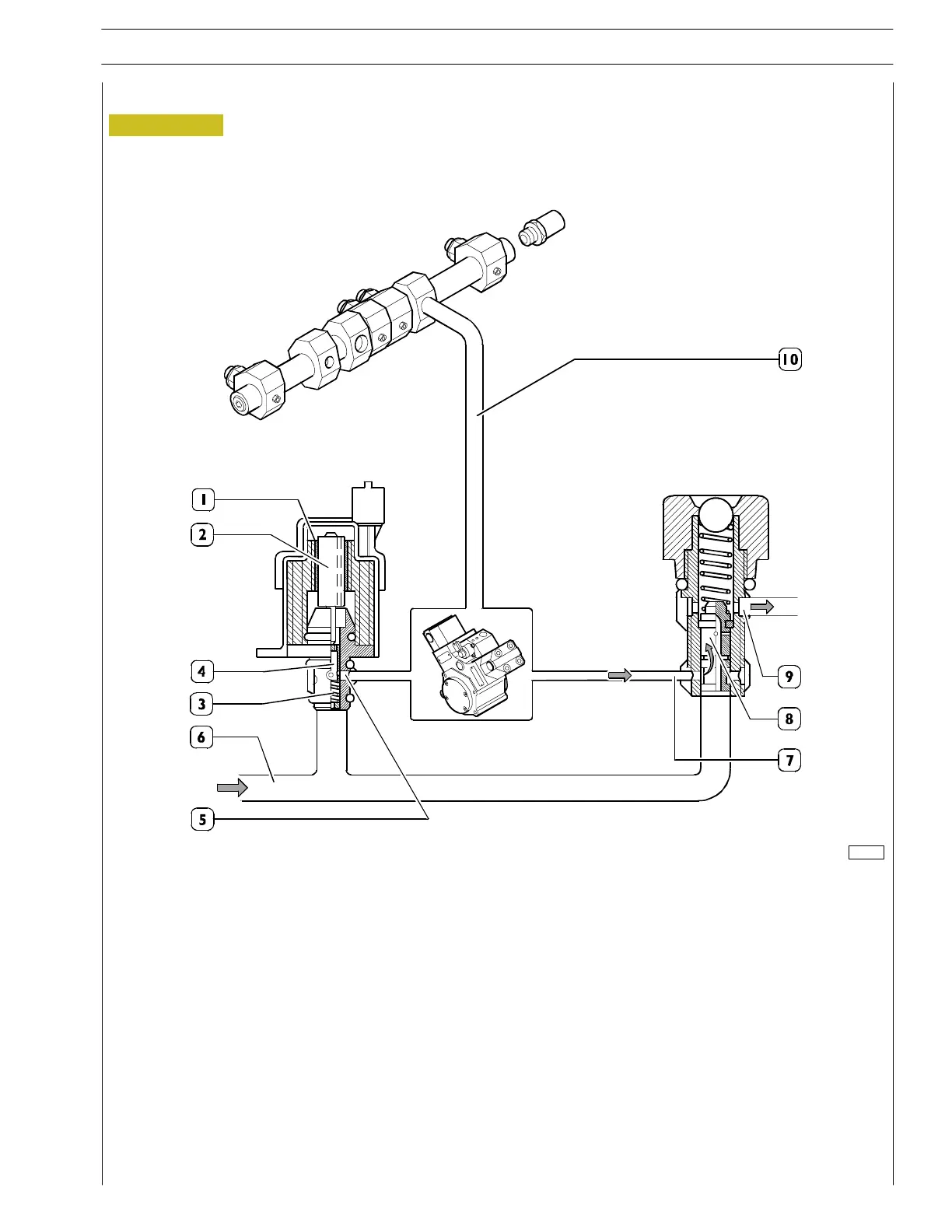
Figure 16
Pressure regulator and 5 bar pressure relief valve at max. fuel delivery
1. Coil — 2. Core — 3. Pre—loading spring — 4. Shutter — 5. High—pressure pump supply — 6. Fuel inlet (from the filter) — 7. Fuel
return from th e high—pressure pump — 8. Cylinder for opening outlet lin e — 9. Fuel outlet — 10. Fuel delivery
When the coil (1) of the regulator is not energised, the core (2) is in the rest position due to the pre—loading spring (3). The
shutter (4) is in th e position of maximum delivery and the HPP will provide the rail with max. pressure.
The clearance between the internal parts in the high pressure pump permits fuel leakage, which is used to lubricate t he pump.
This excess fuel is sent towards the pressure relief valve.
The c ylinder (8) in th e pressure relief valve will then move into a balanc ed position and there it will maintain the pressure in the
low pressure line at 5 bar.
81386
SECTION 2 - FUEL
19
VECTOR 8 ENGINES
Print P2D32V001E Base - April 2006
 Loading...
