– 17 –
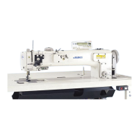
[Wiring of the control box for stitch skipping de-
tecting device]
1) Connect solenoid valve cable
❽
of the air blower
solenoid valve_SD to the CN4.
2) Connect the 16P connector of the junction cable
❶
of the bobbin-thread remaining amount detect-
ing device and stitch skipping detecting device to
the CN1.
3) Connect encoder junction cable asm.
❷
to the
CN3.
4) Connect encoder extension cable asm.
❼
to the
CN2.
5) Connect the stitch skipping detecting device ca-
ble
❾
to the CN8. Put the excess of the cable in
the control box.
6) After the completion of connection of all connec-
tors, close cover
with screw
.
The connectors cannot be connected un-
less the correct order is followed.
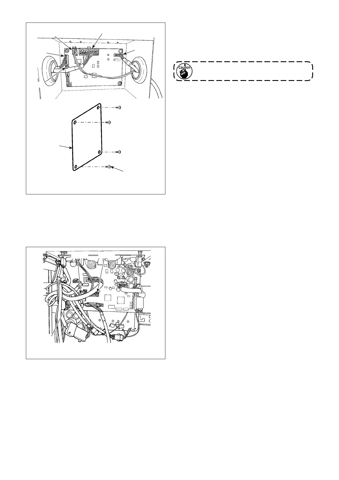
[Wiring of the electrical box (CTL PCB)]
Connect the connectors in the following order refer-
ring to Figs. 1 and 3.
Connect the connectors in the following order refer-
ring to Figs. 1 and 4.
1) Connect the 22P connector of the junction cable
❶
of bobbin-thread remaining amount detecting
device and stitch skipping detecting device to the
CN51.
2) Pull out the connector (motor encoder connector
coming from the sewing machine) from the CN30.
Connect encoder extension cable
❼
to the cable
you have pulled out.
3) Connect encoder junction cable
❷
to the CN30
on PCB side.
4) Connect protection cover sensor cable
❸
to the
CN58.
5) Connect the bobbin-thread remaining amount
detecting device sensor amplier cable
❹
to the
6P connector of junction cable
❶
of the bob-
bin-thread remaining amount detecting device
and stitch skipping detecting device.
6) Connect solenoid valve cable
❻
of the air blower
solenoid valve asm_AE to the 2P connector of
junction cable
❶
of the bobbin-thread remaining
amount detecting device and stitch skipping de-
tecting device.
CN8
CN2
CN4
CN1
CN58
CN51
CN30
[Fig. 3 Control box]
[Fig. 4 Electrical box (CTL PCB)]
CN3
* Connect the cables to the CN1, CN2 and CN3 while inserting the former through the hole in the left
surface of control box. Connect the cables to the CN4 and CN8 while inserting the former through
the hole in the right surface of control box.

 Loading...