TS-990S
10
CIRCUIT DESCRIPTION
3. Main Receiver Circuit
3-1. From the Antenna Terminal to the Preselector
Amplifi er (Q10 and Q11)
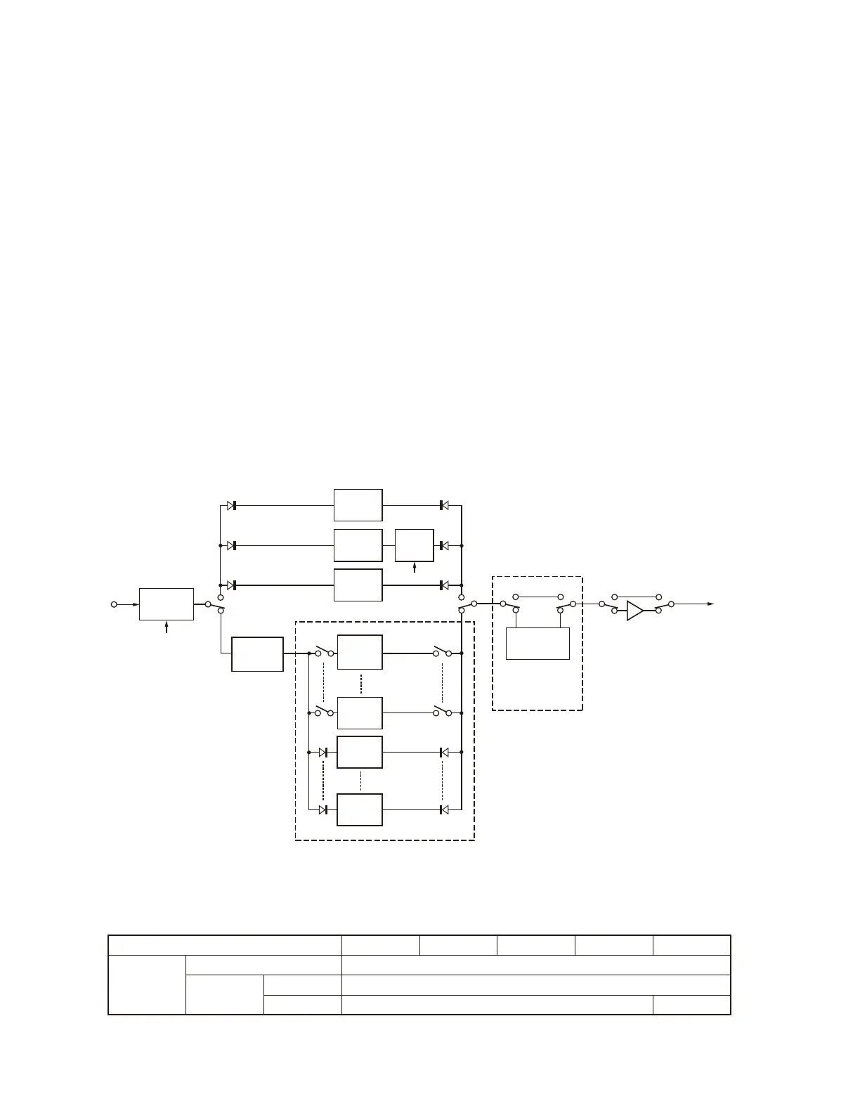
Figure 5 shows a front part of the block diagram for the
main receiver circuit.
A double conversion is adopted for the main receiver
process so that the 8.248MHz is used for the 1st IF and the
24kHz (FM: 455kHz) is used for the 2nd IF frequency (Refer
to table 4).
The received signal from ANT1~ANT4 is fed to CN1
(MRAT) via K801 to 804 relays on the antenna connector
unit (X45-388 B/2) and K18, K19, K10, K14 relays on an-
tenna switch unit (X53-441 A/2). (Fig. 28)
A received signal enters CN1 (MRAT) on the RX unit
(X55-313 A/2). The signal input to the RX unit is fed to the
ATT (OFF/6dB/12dB/18dB) selector, and is fed to the BPF
unit (X55-313 B/2) via the surge current absorbing limiter,
BC band attenuator (except 30kHz to 1.705MHz and 35 to
40MHz). The two traps (11.7MHz and 15.5MHz) are embed-
ded in the BC trap in order to prevent interference from high
power broadcast stations.
The BPF divides in the range as shown in table 5. BPFs
for 30kHz to 1.705MHz and 35 to 40MHz are mounted on the
RX unit, and BPFs for 1.705 to 60MHz (except 35 to 40MHz)
are mounted on the BPF unit. In major amateur bands, the
toroidal coils and air core inductor are used to reduce in-
sertion loss in the passband by the BPF, and the relay is
used to suppress distortion by a large signal for the switch.
In order to prevent intermodulation ranging from 522kHz to
1.705MHz due to high power broadcasting stations, the ATT
(attenuator) is mounted (ATT ON: CN50=open, CN60=short
/ ATT OFF: CN50=short, CN60=open).
The signal passed through the BPF is applied to the
PRESEL unit (X42-343 B/10) where a preselector (tuning
circuit of the single-peaked characteristic) that can be se-
lected with a preselector key ([P.SEL] key) is mounted.
The preselector makes it possible to improve the selectiv-
ity of the receiver. If the preselector is selected, the preselec-
tor amplifi er (Q10 and Q11) will be selected where the signal
attenuated in the preselector will be compensated for.
Fig. 5 Front part of the main receiver circuit
Mode SSB CW FSK AM FM
RX-1 path
Conversion method Double
IF frequency
1st 8.248MHz
2nd 24kHz 455kHz
Table 4
Mode, conversion method, and IF frequency
AT T
AT T
–6dB/12dB
/18dB
AT T
AT T
BC Trap
BPF
BPF
LPF
522kHz~
1.705MHz
LPF
30kHz~
522kHz
BPF
BPF
Q10,Q11
PRESEL AMP
Preselector
To PRE AMP
PRESEL unit
(X42-343 B/10)
BPF unit
(X55-313 B/2)
MRAT
BPF
35MHz~
40MHz
 Loading...