TS-990S
161
ADJUSTMENT
■
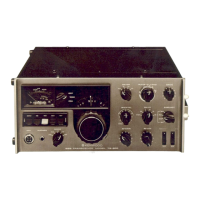
Rear panel
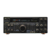
Service Jig
1. ACC 2 connector short plug
Use the same adjustment jig as the TS-570.
■
How to use the ACC 2 connector short plug
Insert the adjustment jig into the ACC 2 connector locat-
ed on the rear panel of the transceiver.
2. Adjustment rod (W05-1770-00/ HOZAN: D-272)
Use the adjustment rod when adjusting the 14.1MHz Null
point.
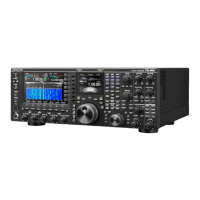
■
Adjustment method using the adjustment rod
1) Insert the adjustment rod into the hole of the antenna
connector unit (X45-388 B/2) as shown in the fi gure.
2) Perform the adjustment after inserting the tip of the ad-
justment rod in TC1 of the antenna switch unit (X53-441
A/2) which is mounted in the lower part of the antenna
connector unit.
Adjustment rod
Antenna connector unit
(X45-388 B/2)
Antenna switch unit
X53-441 A/2
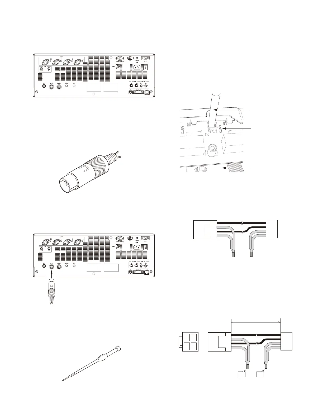
3. Jig cable (W05-1772-00)
Use the jig cable when adjusting the fi nal idling current.
1
2
1
4
3
4
■
The modifi cation method when using the lead
wire with connector (E37-1611-05)
1) Cut the center part of the red lead wires (pins 1 and 2) of
the cable (E37-1611-05).
2) Bundle and solder the tips of each lead wire (parts C and D)
as shown in the fi gure.
3
4
1
2
1
2
L=180±5mm
1
4
3
4
C
D
 Loading...