TS-990S
14
CIRCUIT DESCRIPTION
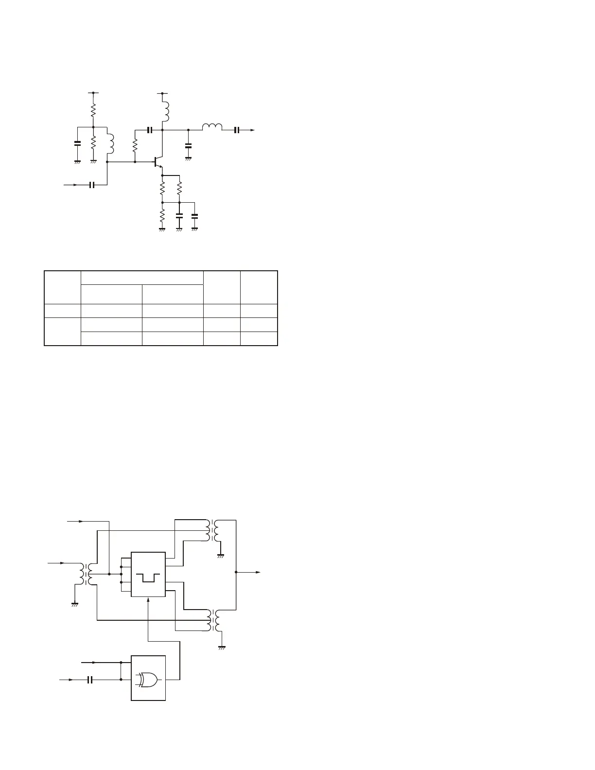
3-6. 1st Mixer
The 1st mixer is of double balanced grounded switch type
incorporating the bus switch (IC7) and logic driver (IC8), and
the signal from the 1st mixer is mixed with the MLO1 (8.278
to 51.752MHz) at a level of approximately +10 dBm and is
converted into the 1st IF (8.248MHz).
A bias voltage of 2.5 V from the bus switch is applied to
IC7 and a voltage of 2.5 V for duty ratio determination is ap-
plied to IC8.
Table 8 Preamplifi er key display
Fig. 11 Preamplifi er 2 circuit
Screen
display
Circuit operation
Preampli-
fi er gain
Post
amplifi er
Preamplifi er
circuit 1
Preamplifi er
circuit 2
OFF OFF OFF 0dB OFF
P.AMP
ON OFF 9dB ON
OFF ON 22dB ON
Fig. 12 1st mixer circuit
L55
RF
+2.5V
IC7
x4
+2.5V
MLO1
8.278~51.752MHz
IC8
L59
L60
1st IF
8.248MHz
3-7. Noise Blanker Filter and IF Filter Adjustments
Five types of fi lters (MCFs and crystal fi lters) are used
as a noise blanker fi lter and IF fi lters at a center frequency
of 8.248MHz. The noise blanker fi lter (XF1) and the IF fi lters
(XF3, XF4, and XF8) with a passband width of 15kHz, 6kHz,
and 2.7kHz need adjustments. The 500Hz and 270Hz IF
fi lters (XF5 and XF6) incorporate variable inductors, which
are precisely adjusted at the factory before shipping. Users
do not need to adjust them. Adjust the IF fi lters fi rst. Then,
adjust the noise blanker fi lters.
The IF filter (XF3) is a 2-pole MCF and its passband
width is 15kHz. Since the terminating impedance of the IF
fi lter (XF3) is 5.6 k
, it is converted into 50
by the variable
inductors (L94 and L97). Connect an appropriate equipment,
such as a tracking generator, to the IF fi lter adjustment con-
nectors (CN115 and CN129) and turn the variable inductors
(L94 and L97) to adjust the IF fi lter. The IF fi lter (XF4) is a
2-pole MCF, has a passband width of 6kHz and a terminat-
ing impedance of 2.4 k
. The IF fi lter (XF8) is a 2-pole MCF,
has a passband width of 2.7kHz and a terminating imped-
ance of 1.35 k
. Perform the IF fi lter (XF4 and XF8) adjust-
ment in the same manner as the XF3 adjustment. First, con-
nect a tracking generator to CN115 and CN129, the turn the
variable inductors (L95, L98, L96, and L99) to adjust the IF
fi lter.
The noise blanker fi lter (XF1) is the same as the IF fi l-
ter (XF3) with a passband width of 15kHz. Adjustment of
the noise blanker filter (XF1) will be carried out after the
completion of the IF filter adjustment in adjustment mode
with a passband width 15kHz IF fi lter connected. Connect a
tracking generator to the adjustment connectors (CN86 and
CN129), and adjust the variable inductors (L110 and L111)
on the noise blanker filter side. Do not adjust the variable
inductors (L94 and L97) on the IF fi lter side when making
adjustments.
If you have replaced the noise blanker fi lter, such as IF
fi lters (XF1, XF3, XF4, and XF8), variable inductors (L110,
L111, L94, L97, L95, L98, L96, and L99), or the main RX
unit (X55-313 A/2), be sure to perform MCF adjustments in
adjustment mode.
Input
Output
14V
Q20
14V
 Loading...