TS-990S
26
CIRCUIT DESCRIPTION
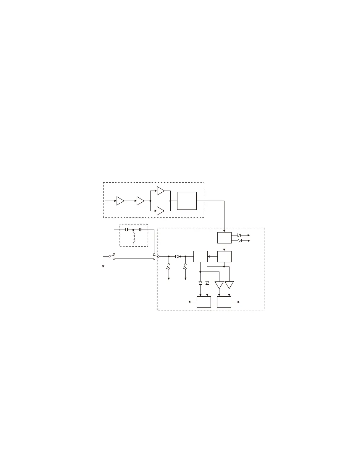
5-2. From the Drive output to the Antenna Terminal
The transmission signal sent to the CN2 (DRIVE) of the
fi nal unit (X45-388 A/2) from the TX-RX unit (X57-827 A/2)
is amplifi ed to the specifi ed power by the fi nal unit and input
into the antenna connector unit (X45-388 B/2) through the
LPF. This transceiver includes a relay antenna tuner circuit
that operates in amateur bands.
The transmission signal that is applied to the CN2 of
the fi nal unit is amplifi ed by the pre-drive amplifi er (Q2) and
drive amplifi er (Q3), and then power amplifi ed by the fi nal
amplifi er (Q7) to 200 W. The harmonic components of the
signal are then removed by the LPF, and the signal is sent to
the antenna switch unit (X53-441 A/2).
The fi nal amplifi er is a push-pull amplifi er consisting of
a power MOS FET (VRF150MP) of 50 V type. Q7 (A/2) and
Q7 (B/2) form a pair that is matched through VGS (TH). Q7
(A/2) and Q7 (B/2) are packaged under a single part num-
ber, therefore both of them need to be replaced even if one
of the push-pull elements is broken.
The signal amplified to 200 W is applied to J7 on the
antenna switch unit (X53-441 A/2) from J1 on the fi nal unit
(X45-388 A/2). The signal goes through the forward/refl ected
wave detector, amplitude/phase detector for the antenna
tuner, transmission/reception switching diode (D19), and
antenna tuner IN/THROUGH switching relay (K18 and K19),
and is sent from J4 on the antenna switch unit.
The signal is applied to J800 on the antenna connector
unit (X45-388 B/2), and is fi nally sent from the ANT1, ANT2,
ANT3, or ANT4 antenna terminal via the antenna switching
relay (K801, K802, K803, or K804). In order to reduce the
operating noise of the transmission/reception switching relay,
the transmission path uses a diode switch and the reception
path uses a relay circuit (as with the TS-940). The relay (K16)
is turned ON during signal reception in order to maintain the
isolation of the transmitter block from the receiver block.
Fig. 27 From the drive output to the antenna terminal
Q2
Q3
Q7(A/2)
Q7(B/2)
TX LPF
1.8-50MHz
BAND
L28
SWR
L25
L24
IC4
IC3
Drive in
VSR
VSF
Phase
defferencial
out
D37
D36
Q26
D19
K9
RAT
K16
GND
Amplitude
defferencial
out
K18
K19
AT in
AT through
X45-388 A/2
X53-441 B/2
X53-441 A/2
Q25
5-3. Antenna Tuner and Various Protections
The antenna tuner is switched by antenna change over
relays (K18 and K19). If IN is selected, the signal is applied
to the antenna tuner unit (X53-441 B/2), where a capacitor
and coil in combination tune the signal. Its operation is the
same as in previous models. IC4's phase error signal switch-
es the input side capacitor of the tuning circuit, and the IC3's
amplitude difference signal switches the output side capaci-
tor. The SWR is decided by calculating the voltage of the
progressive wave (VSF) and that of the refl ected wave (VSR)
with the main MCU (X53-452 IC46).
The transmit signal is applied to the antenna connector
unit (X45-388 B/2), and fi nally sent from antenna terminal
ANT1, ATN2, ANT3, or ANT4 through an antenna switch-
ing relay (K801, K802, K803, or K804). If the main band and
sub band use the same antenna, the signal passes the path
shown in Fig. 28 and the relay switches over the signal. The
distribution circuit distributes approximately half the power
of the receive signal to the main band and the rest to the
sub band. If the main band and sub band use different an-
tennas, the antenna for the main band or the one selected
for transmission is connected through a relay (K801, K802,
K803, or K804) and the antenna selected for the sub band is
connected through a relay (K805, K806, K807, or K808) on
the sub reception side.
The transceiver has RX IN and RX OUT terminals, thus
making it possible to connect an antenna dedicated for re-
ception to the RX IN terminal or an external BPF or trans-
verter to the RX IN or RX OUT terminal. You can activate an
RX ANT function for either the main band or sub band and
 Loading...