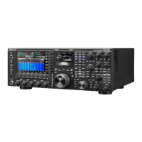
TS-990S
64
SEMICONDUCTOR DATA
Pin No.
Name I/O Function
89 SDTO0 O No connection
90 VDDINT - Core power (1.2V)
91 GND - GND
92 GND - GND
93 VDDEXT - External power (3.3V)
94 NC - No connection
95 GND - GND
96 VDDINT - Core power (1.2V)
97 PDN O Power down for ADC/DAC
98
SCP_
RYBY
I Rady/Busy signal from fl ash memory
99 VDDINT - Core power (1.2V)
100 GND - GND
101 VDDINT - Core power (1.2V)
102 GND - GND
103 VDDINT - Core power (1.2V)
104 GND - GND
105 VDDINT - Core power (1.2V)
106 GND - GND
107 VDDINT - Core power (1.2V)
108 VDDINT - Core power (1.2V)
109 GND - GND
110 VDDINT - Core power (1.2V)
111 GND - GND
112 VDDINT - Core power (1.2V)
113 GND - GND
114 VDDINT - Core power (1.2V)
115 GND - GND
116 VDDEXT - External power (3.3V)
117 GND - GND
118 VDDINT - Core power (1.2V)
119 GND - GND
120 VDDINT - Core power (1.2V)
121 SCDRES I Reset
122 SCDSCS I Serial chip select input from scope MCU
123 GND - GND
124 VDDINT - Core power (1.2V)
125 SCDCLK I Serial clock input from scope MCU
126 SCDSIN O Serial data output to scope MCU
127
SCD-
SOUT
I Serial data input from scope MCU
128 GND - GND
129 VDDINT - Core power (1.2V)
130 VDDEXT - External power (3.3V)
131 AVDD - PLL power (1.2V)
Pin No.
Name I/O Function
132 AVSS - PLL GND
133 GND - GND
134 NC - No connection
135
SCP_
EMU
O For JTAG (no use)
136
SCP_
TDO
O For JTAG (no use)
137 SCP_TDI I For JTAG (no use)
138
SCP_
TRST
I For JTAG (no use)
139
SCP_
TCK
I For JTAG (no use)
140
SCP_
TMS
I For JTAG (no use)
141 GND - GND
142 CLKIN I X'tal input
143 XTAL O X'tal output
144 VDDEXT - External power (3.3V)
Extension Port IC: TC74VHC373FT
(Control unit IC31)
Pin No.
Name I/O Function
1 OE I Output enable
2 SRTS O RTS signal output to scope MCU
3 D0 I Data bit 0
4 D1 I Data bit 1
5 DRTS O RTS signal output to DSP MCU
6 ARTS O RTS signal output to application MCU
7 D2 I Data bit 2
8 D3 I Data bit 3
9 USBSW O
Switch signal for USB device power
H: Active
10 GND - GND
11 LE I Latch enable
12 RT32S O
32kHz clock out control
H: Active
13 D4 I Data bit 4
14 D5 I Data bit 5
15 PRTS O RTS signal output to panel MCU
16 CRTS O RS-232C request to send
17 D6 I Data bit 6
18 D7 I Data bit 7
19 VRTS O RTS signal output to USB-serial bridge
20 VCC - 3.3V

 Loading...


