TS-990S
162
ADJUSTMENT
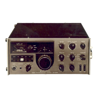
4. Jig cable (W05-1776-00)
Use the jig cable when adjusting the fi nal idling current.
1
4
1
4
■
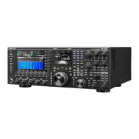
The modifi cation method when using the lead
wire with connector (E37-1612-05)
1) Cut the center part of the yellow lead wire (pin 1) and or-
ange lead wire (pin 3) of the cable (E37-1612-05).
2). Solder the tip of each lead wire (parts C, D, E and F) as
shown in the fi gure.
1
4
L=120±5mm
1
4
C
D
E
F
Adjustment Mode
■
Outline
1. Use two adjustment methods for the transceiver. One
method requires manual adjustments (e.g., coil and trim-
mer adjustments). In the other method, the transceiver is
placed into service adjustment mode, where the trans-
ceiver is adjusted with panel keys. The adjustment items
in Menu 0 to Menu 130 are prepared for the service
adjustment mode (hereinafter referred to as “adjustment
mode”), and adjustment data is stored in two EEPROMs
(X42-343: IC401 and X53-452: IC309).
2. Place the transceiver into adjustment mode and change
the adjustment data on each adjustment item, if neces-
sary.
3. By executing “Write All” in Menu 128, new adjustment data
is written to the EEPROMs. Furthermore, you can write
new adjustment data for each Menu number.
■
Operating Procedure for Adjustment Mode
1. Starting the Adjustment Mode
1) Insert an adjustment jig into the ACC2 connector on the
rear panel of the transceiver.
2) The transceiver is placed into adjustment mode if you turn
ON the power while pressing the [NB1] key and [NR2]
key.
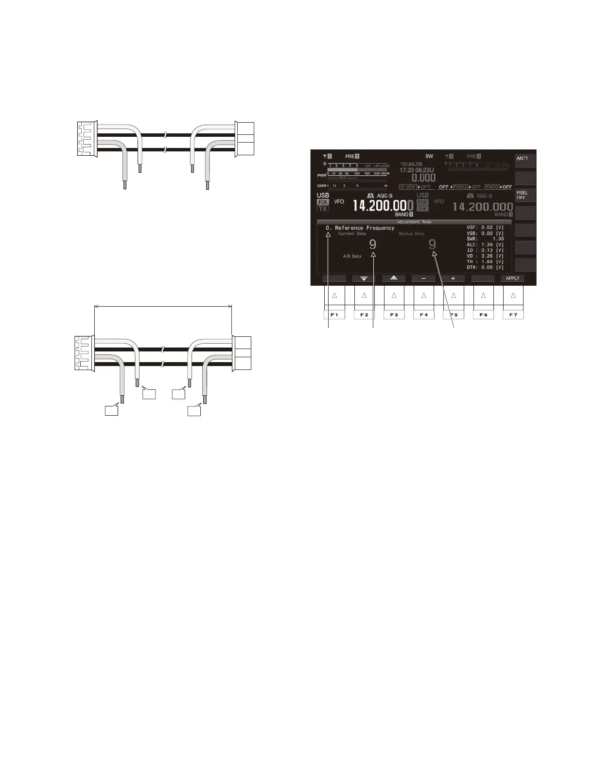
A menu number and adjustment item appear on the
“Adjustment Mode” display in the main screen. When the
menu number appears, remove the adjustment jig from
the transceiver.
Menu No.
Current adjustment value
Value written to EEPROM
2. Changing the Menu Number
Press the [
▲
] (F2)/[
▼
] (F3) keys or rotate the [MULTI/CH]
control to change the menu number.
3. Making Adjustment Data Changes
Press [-] (F4)/[+] (F5)/ [UPDATE] (F5) keys or [UP]/
[DOWN] keys to change the current data (value).
Note: The lower side of the main screen displays [-]/[+]/
[UPDATE] only for adjustment items that require adjust-
ments.
4. Writing Adjustment Data
You can write adjustment data in two ways, as explained
below.
1) Writing Adjustment Data for Each Adjustment Item
If you press the [APPLY] (F7) key for each adjustment
item, the current adjustment data (value) is written to the
corresponding EEPROM (i.e., the backup data value is
replaced with the current data value).
Note: The lower side of the main screen displays [APPLY]
only for adjustment items that require adjustments.
2) Writing Adjustment Data for All Adjustment Items
If you press the [APPLY] (F7) key, [UP] key, or [Down] key
for Menu 128, the current adjustment data is written to
the corresponding EEPROM.
5. Canceling the Adjustment Mode
Press the [CLR] key or [ESC] key to return to the normal
VFO mode display.
Note: The adjustment mode is canceled if you turn OFF
the power.
 Loading...