TS-990S
17
CIRCUIT DESCRIPTION
3-9. Noise Blanker (NB) Circuit
■
Noise Detector
The Noise detector removes pulse noise of short cycle.
The 8.248MHz IF signal passes through the buffer (Q16)
and NB post-amplifi er in the RX unit (X55-313 A/2), and is
sent to the same NB circuit block on the RX unit through the
coaxial cable.
The IF signal passes through the buffer (Q36) in the NB
circuit and is amplifi ed by the 3-stage amplifi er (Q21/Q24,
Q28/Q30 and Q33). The IF signal then passes through the
buffer (Q37) and is noise detected by D21.
A voltage from the noise detector (D21) switches Q35,
turns Q38 ON, attenuates the IF signal in the blanking cir-
cuit (D26 to D29) depending on the noise, and removes the
pulse noise.
The AGC works when a long cycle signal is applied, and
the gains of NB amplifi er 2 (Q21 and Q24), NB amplifi er 3
(Q28 and Q30) and NB amplifi er 4 (Q33) fall, which results
in a low detecting voltage, and Q38 is turned OFF. Thus, the
IF signal is not attenuated. Since the time constant of the
AGC is long, the AGC does not work for short pulses, which
results in a high detecting voltage, and Q38 is turned ON.
Therefore, the blanking circuit operates.
When the NB function is turned ON, a dc voltage MNBL
(threshold control voltage) is applied to the emitter of Q35
from the D/A converter (IC1), so that the Noise Blanking ef-
fect can be adjusted by varying the emitter voltage.
■
Noise Blanking Circuit
The noise blanking circuit attenuates the IF signal by the
signal detected in the noise detector and removes pulse
noises.
When pulse noise is detected in the NB circuit, the
MBLNK goes to “H”, Q54 is turned ON and Q53 is turned
OFF. Diodes D26 to D29 are then turned OFF and the IF
signal is attenuated.
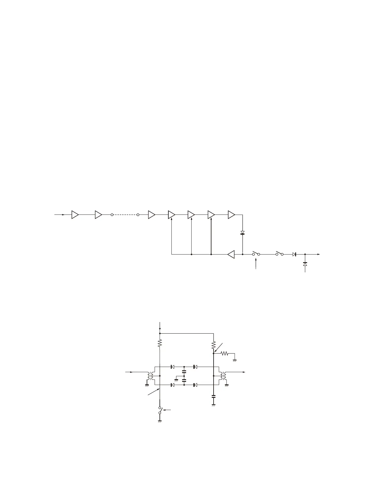
Fig. 14 Noise detection circuit
IF input
(8.248M)
Q16
Buffer
Q18
NB POST AMP
CN80
CN81
Coaxial cable
Q36
Buffer
Q21,24
NB AMP2
Q28,30
NB AMP3
Q33
NB AMP4
Q37
Buffer
D21
Detection
Q32
NB AGC AMP
AGC
MNBL
(Noise blanker
threshold level)
Q35
Switching
Q38
Switching
MIBK
MBLNK signal
(NB blank control)
Fig. 15 Blanking circuit
Blanking OFF : 1.65V
L77
Blanking ON : 1.7V
IN
+8V
L79
Blanking ON : 8V
Blanking OFF : 0V
MBLNK
H : Blanking ON
L : Blanking OFF
OUT
D26 D28
D27
D29
Q53, Q54
 Loading...