TS-990S
27
CIRCUIT DESCRIPTION
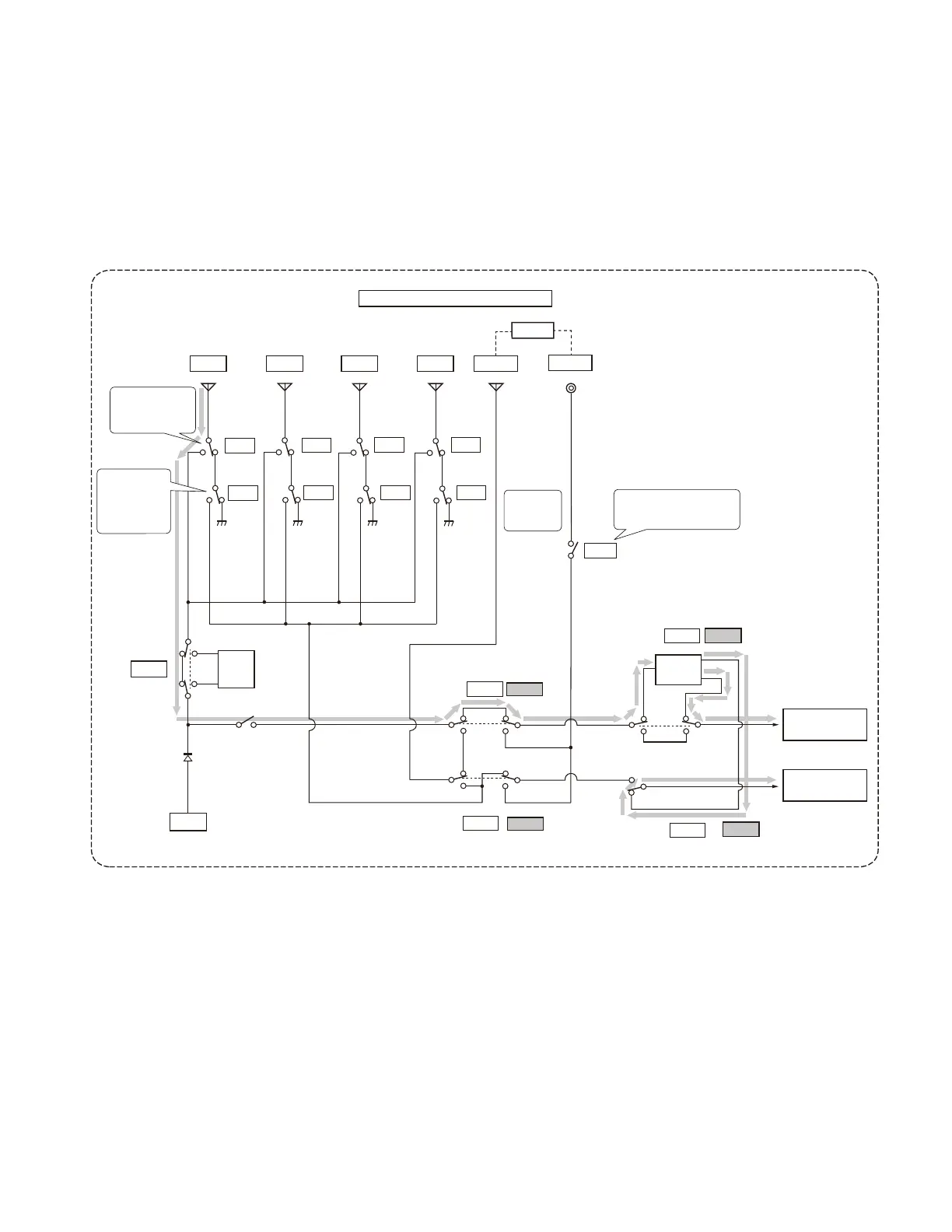
Fig. 28 Antenna distribution diagram
AT
FINAL
AT S
ANT1 ANT2 ANT3
ANT4 RX(OUT)
RX(IN)
BPF etc.
Divider
Loss 3dB
ANT1
ANT2
SANT1
SANT2
SANT3 SANT4
ANT3
ANT4
MRXIO
SRXIO
OFF
OFF
RXANT
OFF
OFF
DIV1
DIV2
(X55-313 A/2 )
X57-827( A/2)
Main : ANT1; Sub : ANT1 (default settings)
K801
K802
K803
K804
K805
K806
K807
K808
K17
K18
K19
D19
K10
K12
K14
K15
RX unit
TX-RX unit
K9
Each relay
shows an
OFF state.
The relays are OFF at the time
of transmission to prevent
the imposing of high power.
ANT switching relay:
Used to switch the
main reception and
transmission paths.
Used to switch the
path if the sub
receiver and main
receiver do not
share the same
path.
connect the antenna dedicated for reception through a relay
(K10, K12, K14, K15, or K17).
This model includes a current protection circuit. The cur-
rent running in the fi nal portion is converted into a potential
difference between the ends of a 5 m
resistor inserted into
the power supply line, and IC5 detects the potential differ-
ence. When the potential difference is larger than a specifi ed
value, IC5 output activates the ALC protection function. This
ALC protection function is controlled so that the current does
not exceed the predetermined value when the current at the
fi nal portion is increased for some unexpected reason. Other
protection circuits include the same as those in previous
models.
Main: ANT1; Sub: ANT1 (default settings)
ANT switching relay: Used to switch the main reception and transmission paths.
Used to switch the path if the sub receiver and main receiver do not share the same path.
Each relay shows an OFF state.
The relays are OFF at the time of transmission to prevent the imposing of high power
 Loading...