TS-990S
11
CIRCUIT DESCRIPTION
Table 5
BPF range
Band Filter range SW
135kHz 30~522kHz Diode
BC 522kHz~1.705MHz Diode
1.8MHz 1.705~2.5MHz Relay
3.5MHz 2.5~4.1MHz Relay
5MHz 4.1~6.0MHz Diode
7MHz 6.0~7.5MHz Relay
10MHz 7.5~10.5MHz Diode
14MHz 10.5~14.5MHz Relay
18MHz 14.5~18.5MHz Diode
21MHz 18.5~21.5MHz Relay
24MHz 21.5~26.5MHz Diode
28MHz 26.5~35MHz Diode
35MHz 35~40MHz Diode
40MHz 40~46.5MHz Diode
50MHz 46.5~60MHz Diode
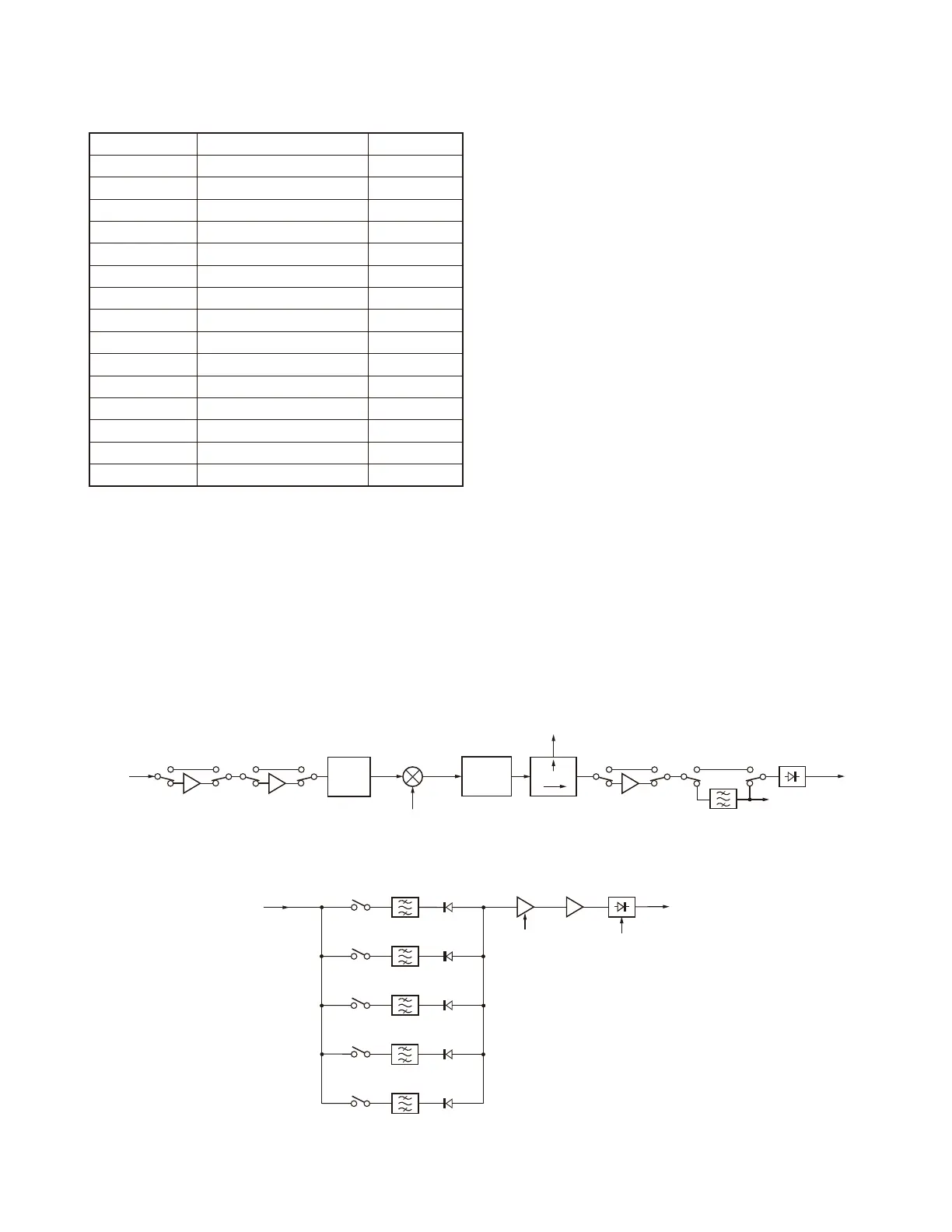
3-2. From the preselector amplifi er (Q10 and Q11)
to the 1st IF frequency (8.248MHz)
The output signal from the preselector amplifi er (Q10 and
Q11) is applied to two amplifi ers, i.e., preamplifi er 2 (Q20)
and preamplifi er 1 (Q25 and Q26) (Refer to Fig. 6). The pre-
amplifi er key ([P.AMP] key) is used to select preamp ON or
OFF. When it is ON, preamplifi er 1 is selected at 30kHz to
21.5MHz received frequency, and the preamplifi er 2 is se-
lected at 21.5 to 60MHz received frequency.
The signal from the preamplifier passes through the
8.248MHz IF trap and is mixed with the MLO1 output (ranging
from 8.278 to 51.752MHz) in the 1st mixer of the double bal-
anced grounded switch type consisting of IC7 and IC8 and
converted into the 1st IF (8.248MHz).
The diplexer enables the wide-band matching of the mix-
er output impedance. The 1st IF signal from the diplexer is
divided into two in the branch circuit, one of which is applied
to the scope unit (X42-343 A/10) and the other is applied to
the post amplifi er (Q46). The post amplifi er is selected only
when the preamplifi ers (preamplifi er 1 or preamplifi er 2) are
ON and has a gain of approximately 8 dB. The 1st IF is ap-
plied to the blanking gate circuit (D26 to D29). If the noise
blanker is ON, the path to the noise blanker filter (2-pole
MCF x 2: XF1) and the noise blanker circuit is active. The
blanking signal by the noise blanker drives the blanking gate
circuit, and the noise is removed. The 1st IF signal passes
through the IF fi lter (roofi ng fi lter). One of 5 fi lters is selected,
depending on the frequency and mode (Refer to Table 6). Al-
though the IF fi lter is usually automatically chosen according
to the DSP fi lter bandwidth, it can also change the IF fi lter
chosen with the fi lter setting menu. An additional roofi ng fi l-
ter prepared by the user can also be set up.
The 1st IF signal passing the IF filter is applied to the
AGC amplifi er (Q70) that uses a dual-gate FET. The AGC
voltage (MAGCV) output from the DSP is applied to the gate
of the AGC amplifi er (Q70). The gain varies by approximately
60 dB with an AGC voltage change. The 1st IF signal is am-
plifi ed by approximately 20 dB in the IF amplifi er (Q49 and
Q52) and passes through the attenuator circuit (D30) using
a PIN diode. The voltage determined while in adjustment
mode is applied to D30 to compensate for the insertion loss
of the IF fi lters (270Hz, 500Hz, 2.7kHz, 6kHz and 15kHz fi l-
ters).
Fig. 6 From the preselector amplifi er (Q10 and Q11) to the 1st IF frequency (8.248MHz)
IC7, IC8
1st Mixer
8.248M
Trap
8.248M 15k
XF3
MAGCV
Q70
AGC AMP
Q49,Q52
IF AMP
8.248M 6k
XF4
8.248M 270
8.248M 2.7k
XF8
8.248M 500
XF5
XF6
MIFGC
IF output
(8.248M)
D30
ATT
Q20
PRE AMP2
From
PRESEL AMP
Q25, Q26
PRE AMP1
8.278~51.752MHz
ML01
Diplexer
Branch
SCOPE
Q46
POST AMP
8.248M 15k
XF1
Noise blanker
Blanking
D26~D29
To IF filters
From Blanking
IF filters
 Loading...