TS-990S
168
ADJUSTMENT
Receiver Section
Item Condition
Measurement Adjustment
Specifi cations/Remarks
Test-
equipment
Unit
Terminal
Unit Parts Method
• Perform the following in the adjustment mode. Item 7, 8, 9, 11, 12, 13 and 22~60.
To terminate the adjustment menu in the middle, save your settings with Menu No. 128.
*1: Do the following preparation prior to the 8.248MHz trap adjustment of the item 1 and adjustments of the item 2~5;
• Remove the Preselector unit from the RX unit.
• Connect CN26 and CN53 using a coaxial cable (E37-1571-15)
1. MAIN RX
Trap fre-
quency
• 1MHz
1) Main display f.:
14.200000MHz
Mode: USB
P.AMP: ON
Spectrum analyzer setting
Start Frequency: 0MHz
Stop Frequency: 2MHz
TG level: 0dBm
Disconnect the cable from
CN1 and connect the track-
ing generator output to CN1.
Disconnect the cable from
CN11 and connect the spec-
trum analyzer input to CN1.
Tracking
generator
Spectrum
analyzer
RX
(A/2)
CN1
CN11
RX
(A/2)
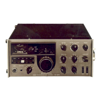
L9 Adjust the coil to get
a null point at 1MHz
as shown.
1.00MHz
• 11.7MHz 2) Main display f.:
14.200000MHz
Mode: USB
P.AMP: ON
Spectrum analyzer setting
Center Frequency: 11.7MHz
Frequency span: 2MHz
TG level: -10dBm
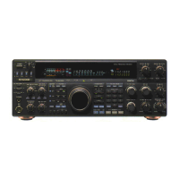
L8 Adjust the coil to
get a null point at
11.7MHz as shown.
11.700MHz
• 15.501MHz 3) Main display f.:
14.200000MHz
Mode: USB
P.AMP: ON
Spectrum analyzer setting
Center Frequency:
15.501MHz
Frequency span: 2MHz
TG level: -10dBm
After the adjustment, discon-
nect the cable from CN11,
and connect the original
cable.
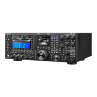
L7 Adjust the coil to
get a null point
at 15.501MHz as
shown.
15.501MHz
• 8.248MHz
(adjustment
1) *1
4) Main fi splay f.: 7.200000MHz
Mode: USB
P.AMP: ON
Spectrum analyzer setting
Center f.: 8.248MHz
Frequency span: 1MHz
TG level: 0dBm
Disconnect the cable from
CN93 and connect the spec-
trum analyzer input to CN93.
CN1
CN93
TC1
TC2
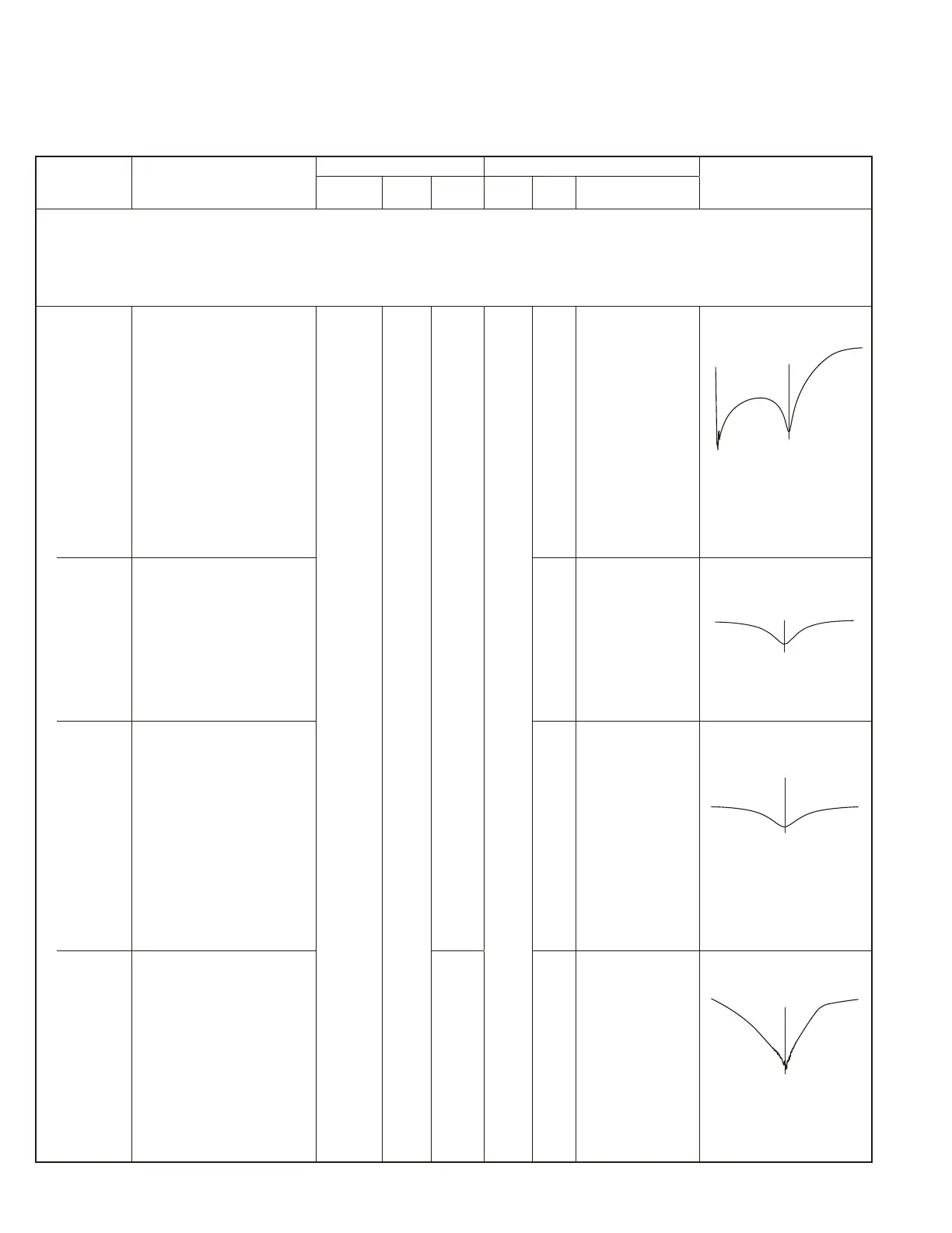
Adjust each trimmer
to get a null point at
8.248MHz as shown.
8.248MHz
 Loading...