SEN03766-02 00 Index and foreword
22
PC130-8
q
95, 125 – 170, 12V140 engines
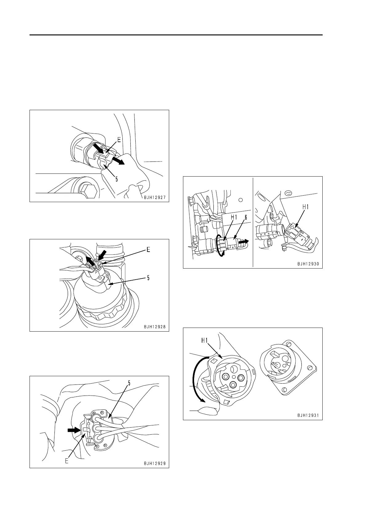
4) While pressing lock (E) of the connector,
pu
ll out connector (5) in the direction of
the arrow.
Example)
Fuel pressure sensor in common rail:
PF
U
EL etc. (AMP-3)
Example)
Injection pressure control valve of fuel
su
ppl
y pump: PCV (SUMITOMO-2)
Example)
Speed sensor of fuel supply pump:
G (S
UMITOMO-3)
a Pull the connector straight up.
4
. Turn-housing type (Round green connector)
q
140 engine
Example)
Intake air pressure sensor in intake mani-
fold (CANNON-04): PIM etc.
1) Disconnect connector (6) according to the
foll
owi
ng procedure.
1] Turn housing (H1) in the direction of
the ar
row.
a When connector is unlocked,
ho
using (H1) becomes heavy to
turn.
2] Pull out housing (H1) in the direction
of
the
arrow.
a Housing (H1) is left on the wiring har-
ne
ss side.
2) Connect the connector according to the
followi
ng procedure.
1] Insert the connector to the end, while
se
tting its groove.
2] Turn housing (H1) in the direction of
the ar
row until it “clicks”.
 Loading...