3.13 WORKING WITH THE ATTACHMENT OPERATION
252
3.13 WORKING WITH THE ATTACHMENT
3.13.1 MACHINES EQUIPPED WITH ”EURO” CONTROL SYSTEM
OTICE
The illustrations show a typical construction of control stand
and working attachment.
However, the shown operation - and working movements
apply to this machine.
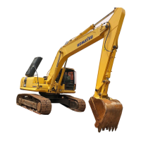
BACKHOE
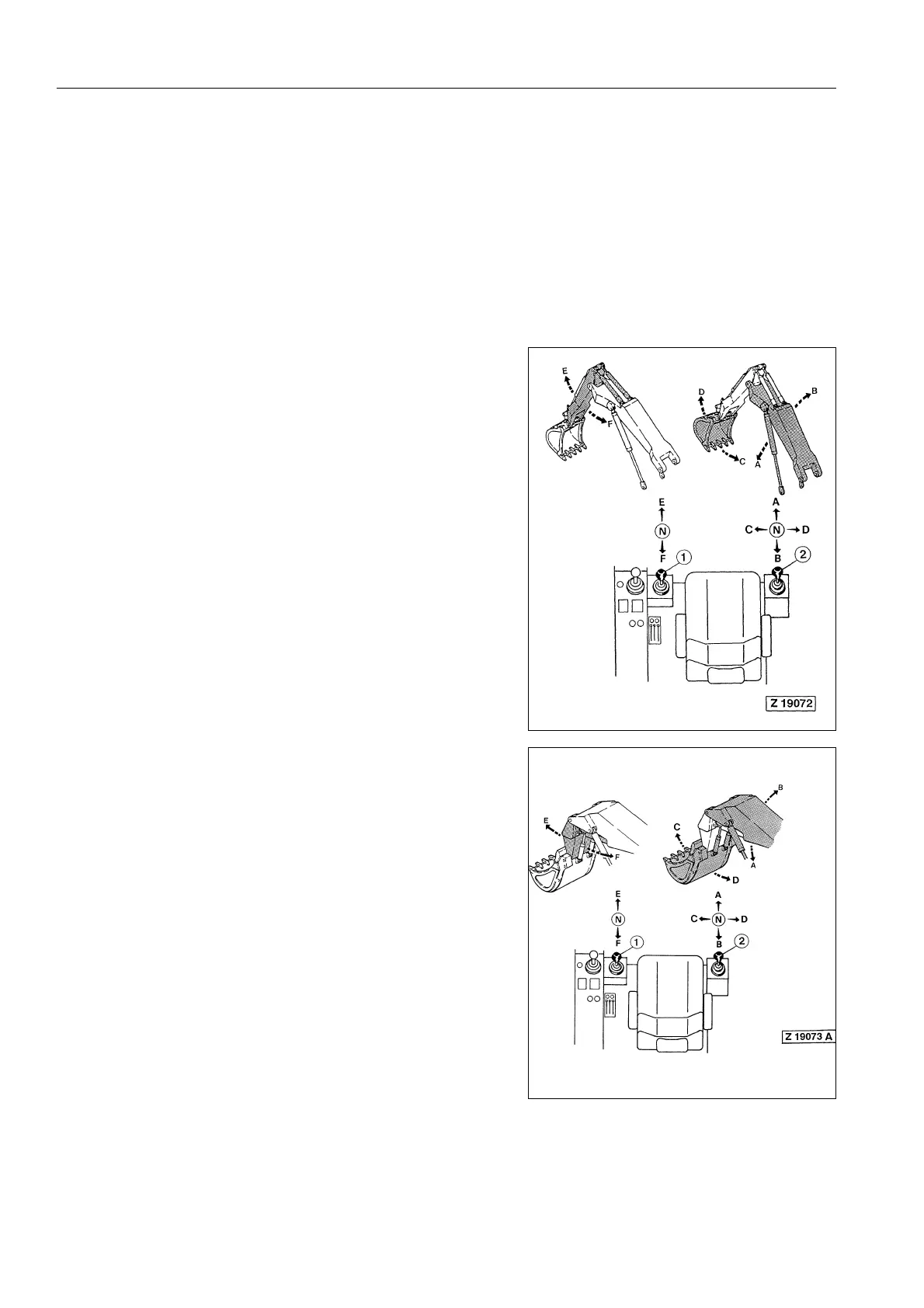
FACE SHOVEL
OTICE
The raised working attachment can also be lowered with the
ENGINE at standstill. If, for example, the engine stalls with
the working attachment in a raised position, lowering of the
working attachment is possible by moving control lever (2) to
position (A). The necessary oil pressure for shifting the
spools of the main control valves is provided by a pressure
accumulator in the pilot oil circuit. After stopping the engine,
relieve the pressure in the hydraulic system.
For more information → See "STOPPING THE ENGINES"
on page 264.
LH control lever(1) RH control lever (2)
E Extending stick A Lowering boom
F Retracting stick B Lifting boom
C Filling bucket
(roll back)
D Emptying bucket
(roll forward)
LH control lever (1) RH control lever (2)
E Extending stick A Lowering boom
F Retracting stick B Lifting boom
C Filling bucket
(roll forward)
D Emptying bucket
(roll back)

 Loading...