3.13 WORKING WITH THE ATTACHMENT OPERATION
258
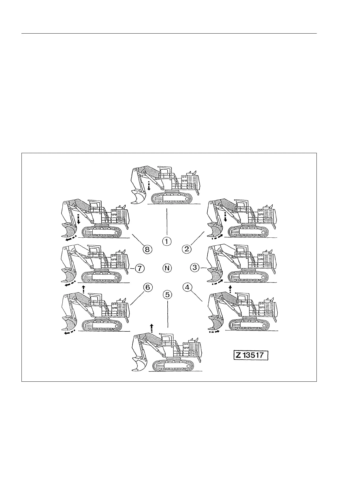
3.13.5 COMBINED OPERATION CYCLES
With each of the control levers, two operation cycles can be initi-
ated simultaneously. In order to obtain efficient operation, always
select intermediate control lever positions in relation to work load.
OTICE
The illustration shows a typical Shovel.
The movements shown in the illustration are controlled:
● at KMG control system with L.H. lever
● at EURO control system with R.H. lever
Legend for illustration Z 13517
(N) Neutral position (5) Raising boom
(1) Lowering boom (6) Raising boom and filling bucket
(2) Lowering boom and emptying bucket (7) Filling bucket
(3) Emptying bucket (8) Lowering boom and filling bucket
(4) Raising boom and emptying bucket
 Loading...