RUNNING GEAR OPERATION
34
Operating instructions • Load Carrier • 505410638-02 • 07/2019
► Check the cleanliness and integrity of
the sealing surfaces on the coupling
heads. Clean if necessary.
► Always connect the brake compressed
air coupling first.
► Connect the supply compressed air
coupling.
► Connect the power supply (vehicle
lighting) and the brake power supply
(EBS).
ü The supply and control connections
are now connected.
Disconnecting C-coupling heads
þ The parking brake on the tractor unit is
applied.
þ The parking brake on the trailer is ap-
plied (see "5.9.2 Parking brake", pg.37).
► Always disconnect the supply com-
pressed air coupling first.
► Disconnect the brake compressed air
coupling.
► Disconnect the power supply (vehicle
lighting) and the brake power supply
(EBS).
ü The supply and control connections
are disconnected.
5.7 Blind couplings
NOTE
Sagging supply and control connec-
tions can cause material damage!
Sagging supply and control connections
can become contaminated on unhitched
trailers,thereby causing material damage.
► On unhitched trailers, always plug the
lines and plugs of all supply and con-
trol connections into their designated
blind couplings.
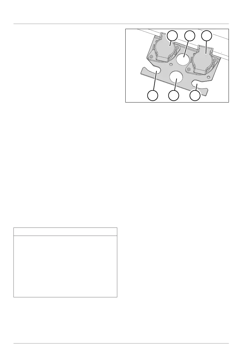
Fig.5-17: Possible arrangement of the sup-
ply and control connections on a
blind coupling
1 EBS plug
2 Plug (white), 7-pin
3 Plug, 15-pin
4 Brake coupling
5 Plug (black), 7-pin
6 Compressed air supply coupling
► Close the coupling heads.
► Place the supply and control connec-
tions on the brackets.
► Insert the cable plugs into their desig-
nated blind plugs.
ü The supply and control connections
are secured.

 Loading...