LOADING AND SECURING
Operating instructions • Load Carrier • 505410638-02 • 07/2019
97
ing blocks and are attached at the required
location on the load securing rails (see "8.4
Load securing rail", pg.96).
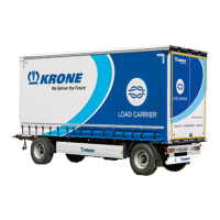
Fig.8-5: Attach the telescopic lock rod
1 Load securing rail
2 Telescopic lock rod
Inserting the telescopic lock rod
► Attach the end of the telescopic lock
rod with the sliding block at the desired
position on the load securing rail.
► Push the telescopic lock rod together
in the direction of the sliding block and
insert the telescopic lock rod at the
corresponding position in the load se-
curing rail on the opposite side.
ü The telescopic lock rod has been in-
serted.
Removing the telescopic lock rod
► Push the telescopic lock rod together
in the direction of the sliding block and
pull out the telescopic lock rod from
the load securing rail on the opposite
side.
► Remove the telescopic lock rod.
ü The telescopic lock rod has been re-
moved.
8.6 Additional aids
Other aids for load securing are, e.g.:
○ Anti-slip mats, to create the highest
possible friction between the load and
the load compartment (the contact
between the load and the load com-
partment must be raised),
○ Rectangular pieces of wood can be
used for support (wider side as a con-
tact surface),
○ Clamping planks and
○ Partition wall locks.
8.7 Using the Multi Safe system
The Multi Safe system includes various
load securing systems with which the
KRONE trailer can be equipped. Informa-
tion on the Multi Safe systems will be
provided below.
8.7.1 Using the Multi-Lock external
frame
KRONE trailers are equipped with a Multi-
lock external frame with universal load se-
curity possibilities. The lashing holes are
distributed along the whole length of the
vehicle at 100-mm intervals. The Multilock
external frame can support loads of 2,000
daN (~kg) per lashing hole, with a max-
imum total load of 8,000 daN (~kg) over a
length of 1,000 mm.
Fig.8-6: Multilock external frame
1 Lashing hole
 Loading...