10 TUNING THE CHASSIS 31
Guideline
Rebound damping
Comfort 18 clicks
Standard 15 clicks
Sport 12 clicks
Info
Turn clockwise to increase damping; turn counterclockwise to reduce damp-
ing.
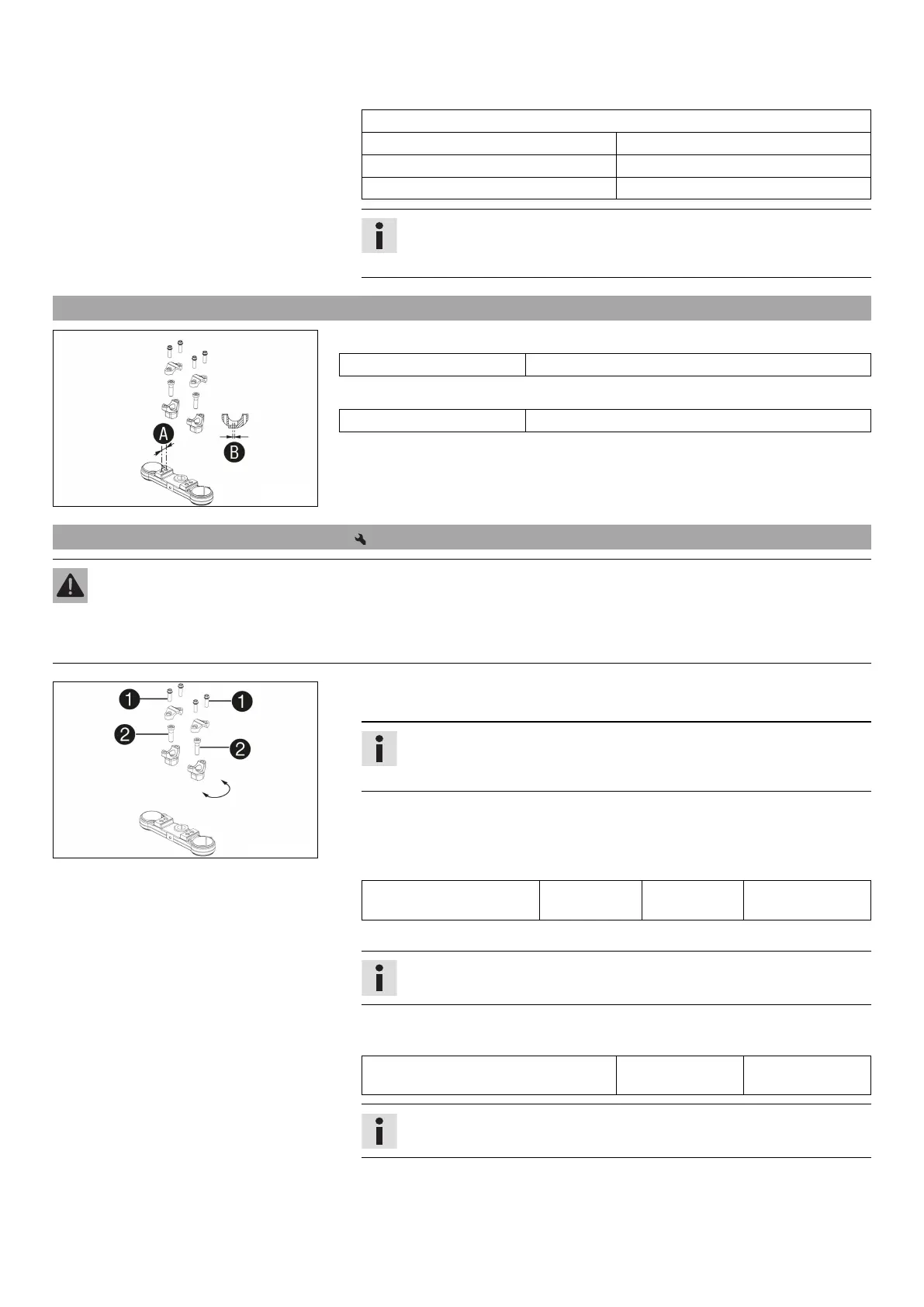
10.14 Handlebar position
C00248-10
On the upper triple clamp, there are two holes at a distance of
to each other.
Hole distance A 15 mm (0.59 in)
The holes on the handlebar support are placed at a distance of
from the center.
Hole distance B 3.5 mm (0.138 in)
The handlebar can be mounted in four different positions. In this way, the handlebar
can be mounted in the position that is most comfortable for the rider.
10.15 Adjusting the handlebar position
Warning
Danger of accidents A repaired handlebar poses a safety risk.
If the handlebar is bent or straightened, the material becomes fatigued. The handlebar may break as a result.
– Change the handlebar if the handlebar is damaged or bent.
C00249-10
–
Remove screws
. Take off the handlebar clamps. Remove the handlebar and lay
it to one side.
Info
Cover the components to protect them against damage.
Do not kink the cables and lines.
–
Remove screws
. Remove the handlebar support.
– Place the handlebar support in the required position. Mount and tighten
screws
.
Guideline
Screw, handlebar support M10 40 Nm
(29.5 lbf ft)
Loctite
®
243™
– Position the handlebar.
Info
Make sure the cables and wiring are positioned correctly.
–
Position the handlebar clamps. Mount screws
and tighten evenly.
Guideline
Screw, handlebar clamp M8 20 Nm
(14.8 lbf ft)
Info
Make sure the gap widths are even.
 Loading...