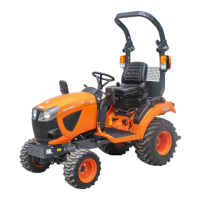
(1) 3-point hitch lowering speed
knob
(A) Fast
(B) Slow
(C) Lock
AUXILIARY HYDRAULIC
CONTROL SYSTEM
1. How to use the auxiliary hydraulic
control valve coupler
WARNING
To avoid serious injury or death:
• Stop the engine and relieve the pressure before
connecting or disconnecting the lines of the
auxiliary-hydraulic-control-valve-coupler.
• Do not use your hands to check for leaks.
Connecting
1. Clean both implement couplers and tractor-
hydraulic-couplers.
2. Remove the dust plugs.
3. Insert the implement couplers to the tractor-
hydraulic-couplers.
4. Pull the implement couplers slightly to make
sure that the implement couplers and the tractor-
hydraulic-couplers are firmly connected.
NOTE :
• Your local KUBOTA Dealer can supply parts for
adapting couplers to hydraulic hoses.
Disconnecting
1. Lower the implement first to the ground to release
the hydraulic pressure in the hoses.
2. Clean the implement couplers and tractor-hydraulic-
couplers.
3. Relieve the pressure by moving the hydraulic-
control-levers with engine shut off.
4. Pull the hydraulic hose straight from the tractor-
hydraulic-couplers to release them.
5. Clean the oil and dust from the implement couplers
and the tractor-hydraulic-couplers.
6. Then replace the dust plugs.
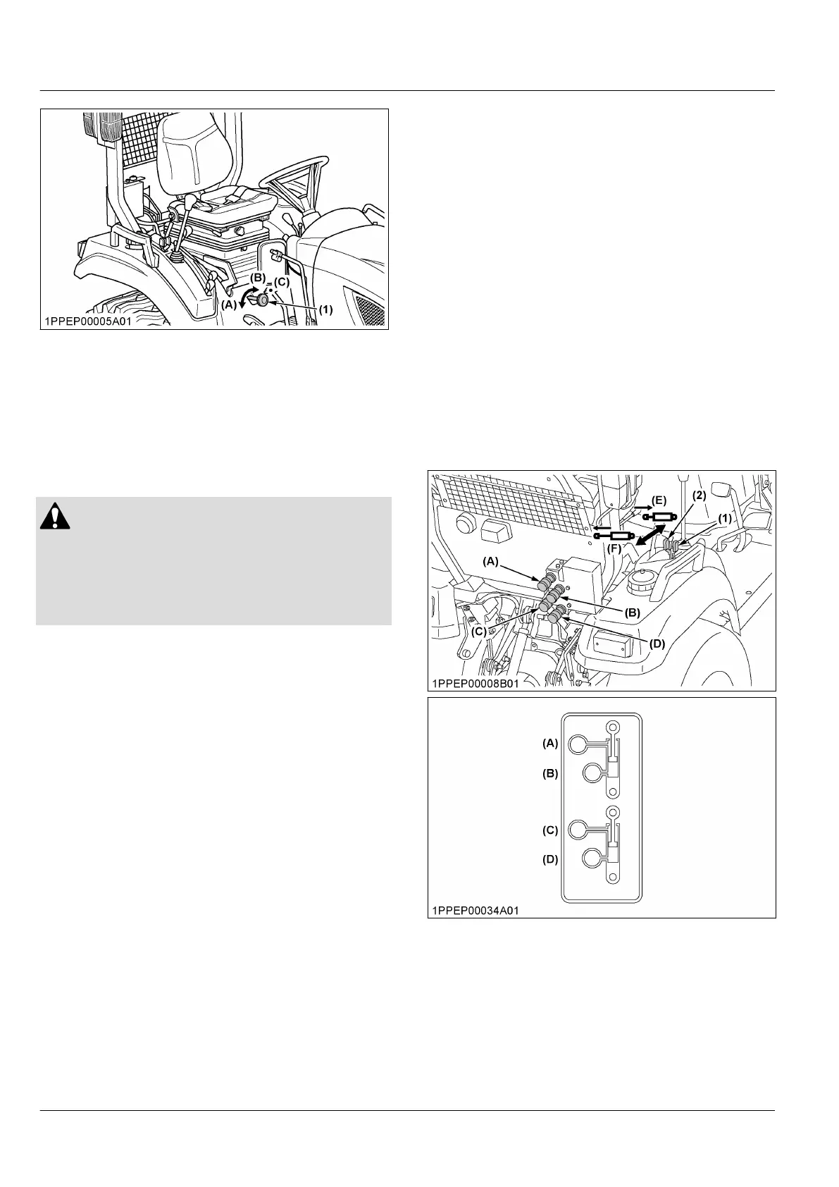
2. Rear auxiliary hydraulic control
lever
• To raise the implement, move the rear-auxiliary-
hydraulic-control-lever to the push position and
hold.
• To lower the implement, move the rear-auxiliary-
hydraulic-control-lever to the pull position and hold.
Rear-auxiliary-hydraulic-control-lever will return to the
neutral position when released.
IMPORTANT :
• Do not hold the rear-auxiliary-hydraulic-control-
lever in the push or pull position once the
remote cylinder has reached the end of the
stroke, because it will cause oil to flow through
the relief valve. Forcing oil through the relief
valve for extended periods will overheat the oil.
• When using the tractor hydraulic system to
power the front loader, do not operate the boom
and bucket cylinders simultaneously.
(1) Rear auxiliary hydraulic con-
trol lever
(2) Rear auxiliary hydraulic con-
trol lever
(A) Port
(B) Port
(C) Port
(D) Port
(E) Push
(F) Pull
HYDRAULIC UNIT AUXILIARY HYDRAULIC CONTROL SYSTEM
 Loading...