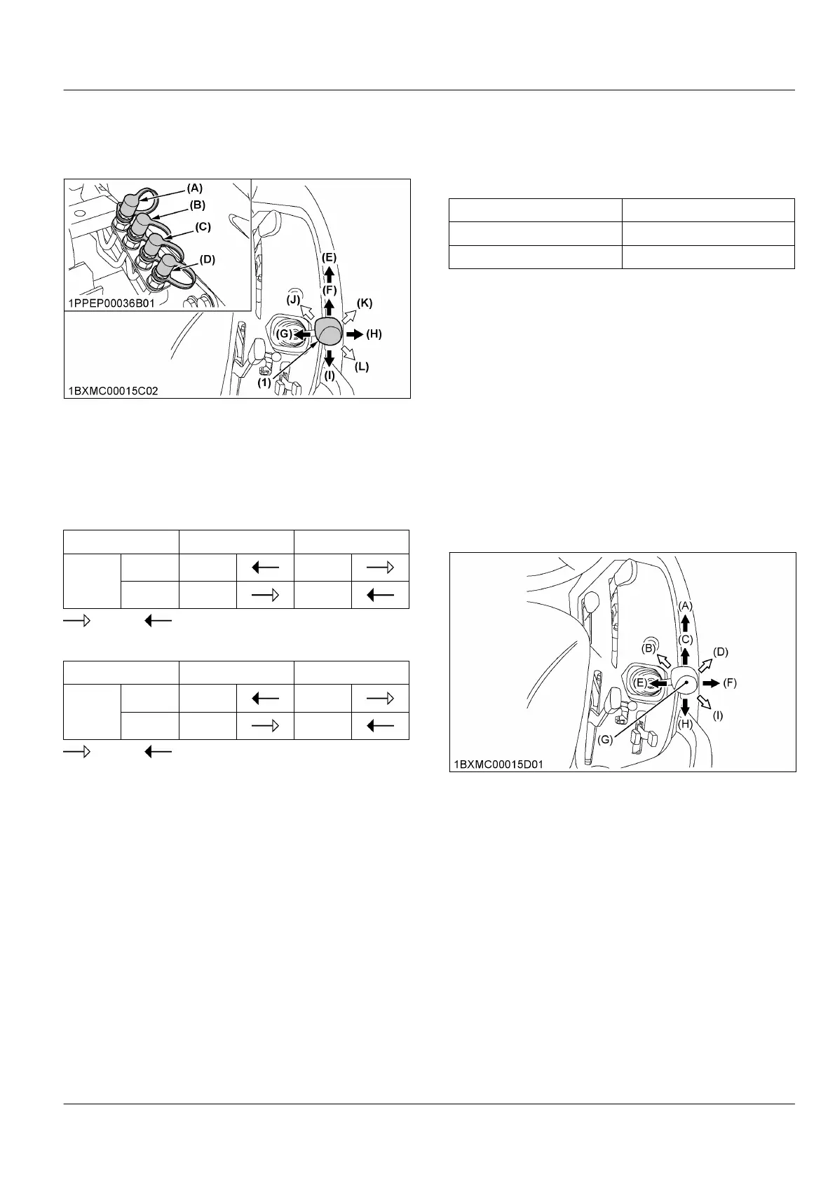
3. Connecting the auxiliary hydraulic
control lever and hydraulic hose to
the auxiliary hydraulic port
(1) Auxiliary hydraulic control
lever (if equipped)
(A) Blue
(B) Red
(C) Yellow
(D) White
(E) Float
(F) Forward
(G) Left
(H) Right
(I) Backward
(J) Forward left
(K) Forward right
(L) Backward right
Hydraulic outlet ports of first segment
Lever Backward Forward
Port
White In Out
Yellow Out In
Pressure, Returning
Hydraulic outlet ports of second segment
Lever
Right Left
Port
Blue In Out
Red Out In
Pressure, Returning
1. Connect the auxiliary-hydraulic-control-lever in its
specified direction and the hydraulic hoses to their
specified ports.
2. Before moving the auxiliary-hydraulic-control-lever,
make sure that the hydraulic hoses for attachments
are connected.
3. Move the auxiliary-hydraulic-control-lever diagonally
(forward left, forward right, and backward right as
shown in the figure).
The first and second segments can be controlled at
once.
NOTE :
• If you move the auxiliary-hydraulic-control-
lever to the float position, it will be held
there by the detent mechanism. To use
the valve as a floating valve with detents,
connect the hydraulic hoses to the white
port and the yellow port.
• Make the following connections when using
this control valve to take off hydraulic power
for the hydraulic cylinder.
Coloured Coupler Hydraulic Cylinder port
Blue and yellow Head-End side
White and red Rod-End side
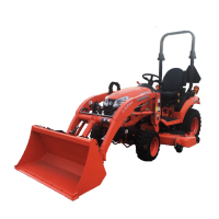
4. Controlling loader (only if
equipped with loader)
• When moving the auxiliary-hydraulic-control-lever
forward, the loader will go down.
• When moving the auxiliary-hydraulic-control-lever
backward, the loader will go up.
• When moving the auxiliary-hydraulic-control-lever
to the left, the bucket will roll back.
• When moving the auxiliary-hydraulic-control-lever
to the right, the bucket will dump.
• When moving the auxiliary-hydraulic-control-lever
diagonally, the loader and bucket will work in the
same time.
(A) Float
(B) Down and roll back
(C) Down
(D) Dump and down
(E) Roll back
(F) Dump1
(G) Normal position
(H) Up
(I) Up and dump
Lower
When lowering the loader, there are 2 stages that
operate the loader differently.
• Down
When shifting the auxiliary-hydraulic-control-lever
forward, the loader will go down with hydraulic
pressure. This lever position is the first stage for
lowering the loader.
• Float
When shifting the auxiliary-hydraulic-control-lever
further forward until feeling the bump, pressure in
the connector lines is released so the loader will go
down by its own weight. This lever position after the
bump is the second stage. When the operator lets
AUXILIARY HYDRAULIC CONTROL VALVE (IF EQUIPPED) HYDRAULIC UNIT
 Loading...