SHOP MANUAL
Paragraphs 9-12
backlash
is
0.15-0.25
mm
(0.006-0.010
inch).
If
measured backlash is excessive,
decrease shims
(15
-
Fig.
16)
on differen-
tial case side and add shims (28)
of
same
thickness between left axle housing and
differential case.
If
backlash
is
insuffi-
cient, decrease shims (28) and
add
same
thickness
to
shims (15).
Complete reassembly
and
installation
of axle assembly. Refill axle housing
with
SAE 90
gear
oil.
DRIVE SHAFT
All Models
So
Equipped
9. Models L305, L345 and L355 use
a
two-piece drive shaft with
a
center
car-
rier bearing (Fig.
22). All
other models
use
a
one-piece drive shaft
as
shown
in
Fig. 21.
Removal
of
drive shaft consists
of
removing mounting screws from drive
shaft tubes, disengaging retaining rings
and sliding drive shaft
out of
couplers.
Remove center carrier bearing
and oil
seals
on
models
so
equipped.
Inspect shaft splines
and
couplers
for
excessive wear
or
other damage.
Reinstall drive shaft
by
reversing
removal procedure.
TRANSFER CASE
All Models
So
Equipped
10.
R&R AND OVERHAUL. Drive
gear (28-
Fig.
28) and idler gear (25) are
located
in
range transmission housing.
Refer
to
appropriate transmission
sec-
tion
for
service procedures.
To service transfer case, first drain
oil
from transmission housing. Disconnect
drive shaft
and
shift linkage. Remove
transfer case mounting
cap
screws
and
lower unit from transmission housing.
To disassemble, remove
oil
seal
(18),
retaining ring
(17) and
plug
(4). Tap
shaft (12)
out
front
of
case
and
remove
gear (14). Drive pin (10) out
of
shift arm
(9)
and
remove shift lever (1).
To reassem ble, reve rse
the
disassembly procedure. Apply liquid
gasket maker
to
surfaces
of
drive case
mounting gasket when reinstalling.
STEERING SYSTEM
MANUAL STEERING
All Models
So
Equipped
All models equipped with manual
steering box
use a
recirculating ball
nut
steering gear similar
to
type shown
in
P^ig.
24.
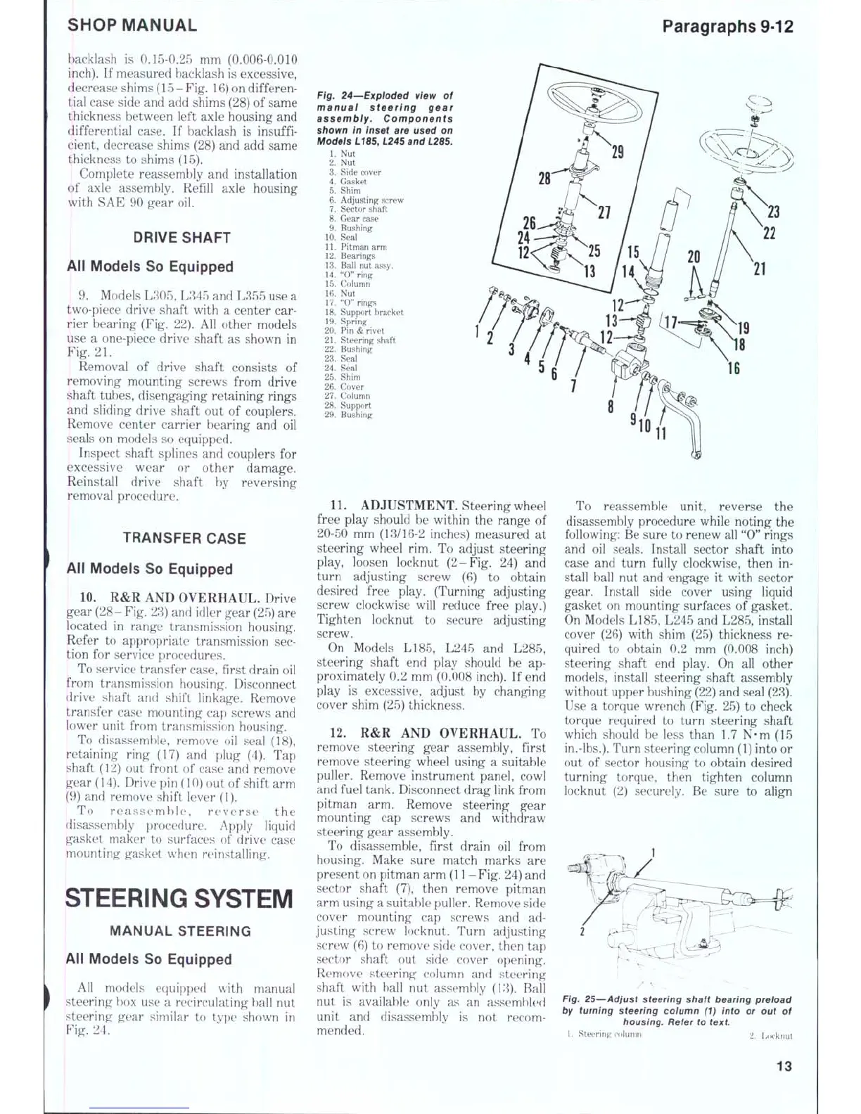
Fig. 24—Exploded view
of
manual steering gear
assembiy. Components
shown
in
inset
are
used
on
Models L185, L245 and
L28S.
1.
Nut
2.
Nut
3.
Side cover
4.
Gasket
5.
Shim
6. Adjusting screw
7.
Sector shaft
8. Gear case
9. Bushing
10.
Seal
11.
Pitman arm
12.
Bearings
13.
Ball nut assy.
14.
"0" ring
15.
Column
16.
Nut
17.
"0" rings
18.
Support bracket
19.
Spring
20.
Pin & rivet
21.
Steering shaft
22.
Bushing
23.
Seal
24.
Seai
25.
Shim
26.
Cover
27.
Column
28.
Support
29.
Bushing
11.
ADJUSTMENT. Steering wheel
free play should
be
within
the
range
of
20-50
mm
(13/16-2 inches) measured
at
steering wheel
rim. To
adjust steering
play, loosen locknut (2-Fig.
24) and
turn adjusting screw
(6) to
obtain
desired free play. (Turning adjusting
screw clockwise will reduce free play.)
Tighten locknut
to
secure adjusting
screw.
On Models LI85, L245
and
L285,
steering shaft
end
play should
be ap-
proximately
0.2
mm (0.008 inch).
If
end
play
is
excessive, adjust
by
changing
cover shim (25) thickness.
12.
R&R AND
OVERHAUL.
To
remove steering gear assembly, first
remove steering wheel using
a
suitable
puller. Remove instrument panel, cowl
and fuel tank. Disconnect drag link from
pitman
arm.
Remove steering gear
mounting
cap
screws
and
withdraw
steering gear assembly.
To disassemble, first drain
oil
from
housing. Make sure match marks
are
present on pitman arm
(1 1-
Fig.
24) and
sector shaft
(7),
then remove pitman
arm using
a
suitable puller. Remove side
cover mounting
cap
screws
and ad-
justing screw locknut. Turn adjusting
screw (6)
to
remove side cover, then
tap
sector shaft
out
side cover opening.
Remove steering column
and
steering
shaft with hall
nut
assembly (13). Ball
nut
is
available only
as an
assernhknl
unit
and
disassembly
is not
recom-
mended.
To reassemble unit, reverse
the
disassembly procedure while noting^
the
following: Be sure
to
renew all "0" rings
and
oil
seals. Install sector shaft into
case
and
turn fully clockwise, then
in-
stall ball
nut and
-engage
it
with sector
gear. Install side cover using liquid
gasket
on
mounting surfaces
of
gasket.
On Models L185, L245 and L285, install
cover
(26)
with shim
(25)
thickness
re-
quired
to
obtain
0.2 mm
(0.008 inch)
steering shaft
end
play.
On all
other
models, install steering shaft assembly
without upper bushing (22) and seal (23).
Use
a
torque wrench (Fig. 25)
to
check
torque required
to
turn steering shaft
which should
be
less than
1.7 N-m (15
in.-lbs.).
Turn steering column (1) into
or
out
of
sector housing
to
obtain desired
turning torque, then tighten column
locknut
(2)
securely.
Be
sure
to
align
Fig. 25—Adjust steering shaft bearing preload
by turning steering coiumn
(1)
into
or out of
housing. Refer
to
text
1.
Steering colunm 2 Ijocknut
13

 Loading...


