SHOP MANUAL
Paragraph 14 Cont.
4 3 2
Fig.
29—Open side of sector shaft
"U"
packing
(3)
should face Inward and open side of seal (4)
should face outward.
1.
Gear housing 3. "I!" packing
2.
Needle bearing 4. Seal
Fig.
30—Be sure
"O"
ring (1)
is installed behind
Teflon
seai
ring (2)
when reinstailing worm shaft
seals in housing.
Fig. 31—View of baii nut seais correctly instail-
ed.
"O"
ring must be behind Tefion rings.
1.
Ball nut assy.
2.
Teflon seal ' 4. "0" ring
3.
Teflon seal 5. "()" ring
Separate components of valve
assembly and inspect for wear, scoring
or other damage. Valve spool (35) and
valve housing (48) must be renewed as a
matched set. Check all components for
Fig. 33—Side cover seai and bearing Installa-
tion.
Be sure open side of
"U"
packing faces
in-
ward.
3.
"IJ" packing
4.
Needle bearing
1.
"O'Ving
2.
Side cover
1
2
3
4
ifi
1!
J
Fig. 34—Upper cover bearing and seal installa-
tion.
Open side of oii seai
(3)
shouid face bearing
(4).
1.
nppor cover 3. "O" ring
2.
Snap ring 4. Bearing
wear and correct fit and renew any
which do not meet the following
specifications: Clearance between
cylinder and ball nut should be
0.030-0.079 mm (0.0012-0.0031 inch).
Worm shaft axial end play in ball nut
should be 0.02 mm (0.0008 inch) and
maximum allowable end play is 0.12 mm
(0.0047 inch). Worm shaft must rotate
smoothly in ball nut. Worm shaft lower
bearing journal outside diameter should
be 28.562-28.575 mm (1.1245-1.1250 in-
ches) with minimum allowable diameter
of 28.475 mm (1.1211 inches). Clearance
between valve housing and spool should
be 0.008-0.015 mm (0.0003-0.0006 inch)
and maximum allowable clearance is
0.025 mm (0.001 inch). Be sure that
spool and sleeve are free of scratches,
nicks or burrs and that spool slides
smoothly in sleeve. Sector shaft bearing
journal diameter should be
38.059-38.075 mm (1.4984-1.4990 in-
ches).
Renew shaft if diameter is less
than 38.025 mm (1.4970 inches).
When renewing needle bearings, posi-
tion bearings in housings so press force
is applied against side of bearing with
manufacturer's marks. Install new oil
seals,
"0" rings and Teflon seal rings as
shown in Figs. 29 through 34. Lubricate
seals and "0" rings prior to reassembly.
Apply molybdenum disulfide "Molycoat"
to steering column bushing(46-Fig. 28)
and oil seal (47).
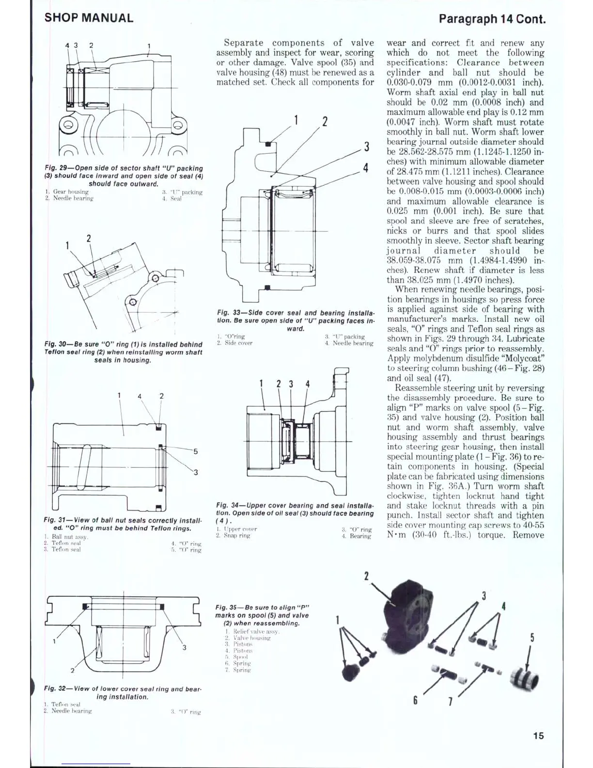
Reassemble steering unit by reversing
the disassembly procedure. Be sure to
align "P" marks on valve spool (5-Fig.
35) and valve housing (2). Position ball
nut and worm shaft assembly, valve
housing assembly and thrust bearings
into steering gear housing, then install
special mounting plate
(1
-
Fig.
36) to re-
tain components in housing. (Special
plate can be fabricated using dimensions
shown in Fig. 36A.) Turn worm shaft
clockwise, tighten locknut hand tight
and stake locknut threads with a pin
punch. Install sector shaft and tighten
side cover mounting cap screws to 40-55
N-m (30-40 ft.-lbs.) torque. Remove
Fig.
32—View of iower cover seai
ring
and bear-
ing installation.
1.
Teflnn sea!
2.
Needle bearing :i. "O" ring
Fig.
35—Be sure to aiign
"P"
marks on spool
(5)
and valve
(2) when reassembiing.
1.
Relief valve assy.
2.
Valve housing
3.
F^istons
4.
F^i.stons
5.
Spool
6. Spring
7.
Spring
6
7
15

 Loading...


