Paragraphs 69-71
KUBOTA
12
1.
Shift lever
2.
Snap ring
3.
Washer
4 .Spring
5.
"0" ring
6. Shield
7.
Shift cover
8. Pins
9. Shield
10.
Balls
11.
Shift rails
12.
Shift fork
13.
Spring
14.
Neutral stops
15.
Shift fork
16.
Shift fork
17.
Detent ball
18.
Detent spring
19.
Shift arm (pto)
20.
Shift rail
21.
Shift fork (range)
22.
Spring
23.
Detent ball
24.
Shift arm
25.
"0" ring
26.
Retaining pin
27.
Shaft retainer
28.
Range shift lever
29.
Set screw
30.
"0" ring
31.
Pto sbift lever
32.
Shift fork (pto)
33.
Shift rail
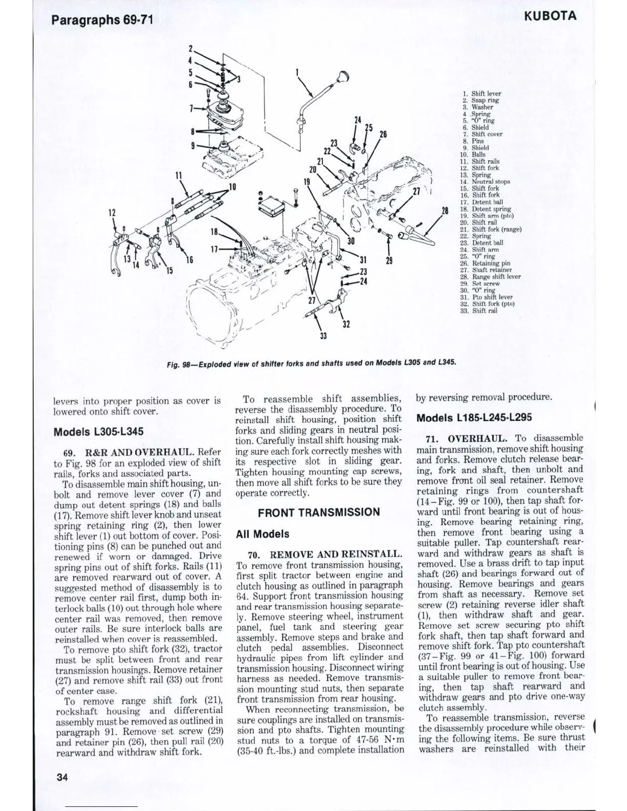
Fig. 98—Exploded view of shifter forks and shafts used on Models L305 and L345.
levers into proper position as cover is
lowered onto shift cover.
Models L305-L345
69.
R&R AND OVERHAUL. Refer
to Fig. 98 for an exploded view of shift
rails,
forks and associated parts.
To disassemble main shift housing, un-
bolt and remove lever cover (7) and
dump out detent springs (18) and balls
(17).
Remove shift lever knob and unseat
spring retaining ring (2), then lower
shift lever (1) out bottom of cover. Posi-
tioning pins (8) can be punched out and
renewed if worn or damaged. Drive
spring pins out of shift forks. Rails (11)
are removed rearward out of cover. A
suggested method of disassembly is to
remove center rail first, dump both in-
terlock balls (10) out through hole where
center rail was removed, then remove
outer rails. Be sure interlock balls are
reinstalled when cover is reassembled.
To remove pto shift fork (32), tractor-
must be split between front and rear
transmission housings. Remove retainer
(27) and remove shift rail (33) out front
of center case.
To remove range shift fork (21),
rockshaft housing and differential
assembly must be removed as outlined in
paragraph 91. Remove set screw (29)
and retainer pin (26), then pull rail (20)
rearward and withdraw shift fork.
To reassemble shift assemblies,
reverse the disassembly procedure. To
reinstall shift housing, position shift
forks and sliding gears in neutral posi-
tion. Carefully install shift housing mak-
ing sure each fork correctly meshes with
its respective slot in sliding gear.
Tighten housing mounting cap screws,
then move all shift forks to be sure they
operate correctly.
FRONT TRANSMISSION
All Models
70.
REMOVE AND REINSTALL.
To remove front transmission housing,
first split tractor between engine and
clutch housing as outlined in paragraph
64.
Support front transmission housing
and rear transmission housing separate-
ly. Remove steering wheel, instrument
panel, fuel tank and steering gear
assembly. Remove steps and brake and
clutch pedal assemblies. Disconnect
hydraulic pipes from lift cylinder and
transmission housing. Disconnect wiring
harness as needed. Remove transmis-
sion mounting stud nuts, then separate
front transmission from rear housing.
When reconnecting transmission, be
sure couplings are installed on transmis-
sion and pto shafts. Tighten mounting
stud nuts to a torque of 47-56 N-m
(35-40 ft.-lbs.) and complete installation
by reversing removal procedure.
Models L185-L245-L295
71.
OVERHAUL. To disassemble
main transmission, remove shift housing
and forks. Remove clutch release bear-
ing, fork and shaft, then unbolt and
remove frcmt oil seal retainer. Remove
retaining rings from countershaft
(14-Fig, 99 or 100), then tap shaft for-
ward until front bearing is out of hous-
ing. Remove bearing retaining ring,
then remove front bearing using a
suitable puller. Tap countershaft rear-
ward and withdraw gears as shaft is
removed. Use a brass drift to tap input
shaft (26) and bearings forward out of
housing. Remove bearings and gears
from shaft as necessary. Remove set
screw (2) retaining reverse idler shaft
(1),
then withdraw shaft and gear.
Remove set screw securing pto shift
fork shaft, then tap shaft forward and
remove shift fork. Tap pto countershaft
(37-Fig. 99 or 41-Fig. 100) forward
until front bearing is out of
housing.
Use
a suitable puller to remove front bear-
ing, then tap shaft rearward and
withdraw gears and pto drive one-way
clutch assembly.
To reassemble transmission, reverse
the disassembly procedure while observ-
ing the following items. Be sure thrust
washers are reinstalled with their
34

 Loading...


