SHOP MANUAL
Paragraphs 119-120
NOTE:
Test bar can be fabricated using
dimensions given in Fig. 159.
Use a spring scale attached at top of
control lever to check control lever fric-
tion adjustment. It should require
1.5-3.5
kg (3.4-7,5 pounds) to move con-
trol lever. To adjust, tighten or loosen
control lever shaft nut.
PUMP
Models L185-L235-L245-L275-
L285-L295
119.
R&R AND OVERHAUL.
Gear-type hydraulic pump is mounted on
right side of engine and gear driven
from rear of injection pump camshaft.
To remove pump, disconnect suction and
discharge pipes from pump. Remove
pump mounting cap screws and stud
nuts,
then slide pump rearward off drive
housing. Cover suction and discharge
pipe openings to prevent entry of dirt.
To disassemble pump, remove retain-
ing nut and drive gear on Models L185
and L245. On all models, scribe a match
mark across end cover and pump body
to ensure correct reassembly. Remove
end cover mounting screws, then
carefully separate cover and com-
ponents as shown in Fig. 160. Be sure to
identify location of bushings (5) and
driven gear (7) so they can be reinstalled
in their original positions. Bushings
should not be interchanged. Remove oil
seal (2) from pump body and discard all
seal rings.
Radial clearance between tip of gear
tooth and inside diameter of pump body
should not exceed 0.05 mm (0.002 inch)
on Models LI85, L245, L285 and L295
or 0.15 mm (0.006 inch) on Models L235
and L275. Renew pump if clearance is
excessive. Maximum allowable
clearance between bushings (5) and gear
shafts is 0.18 mm (0.007 inch) on Models
L185,
L245, L285 and L295 or 0.12 mm
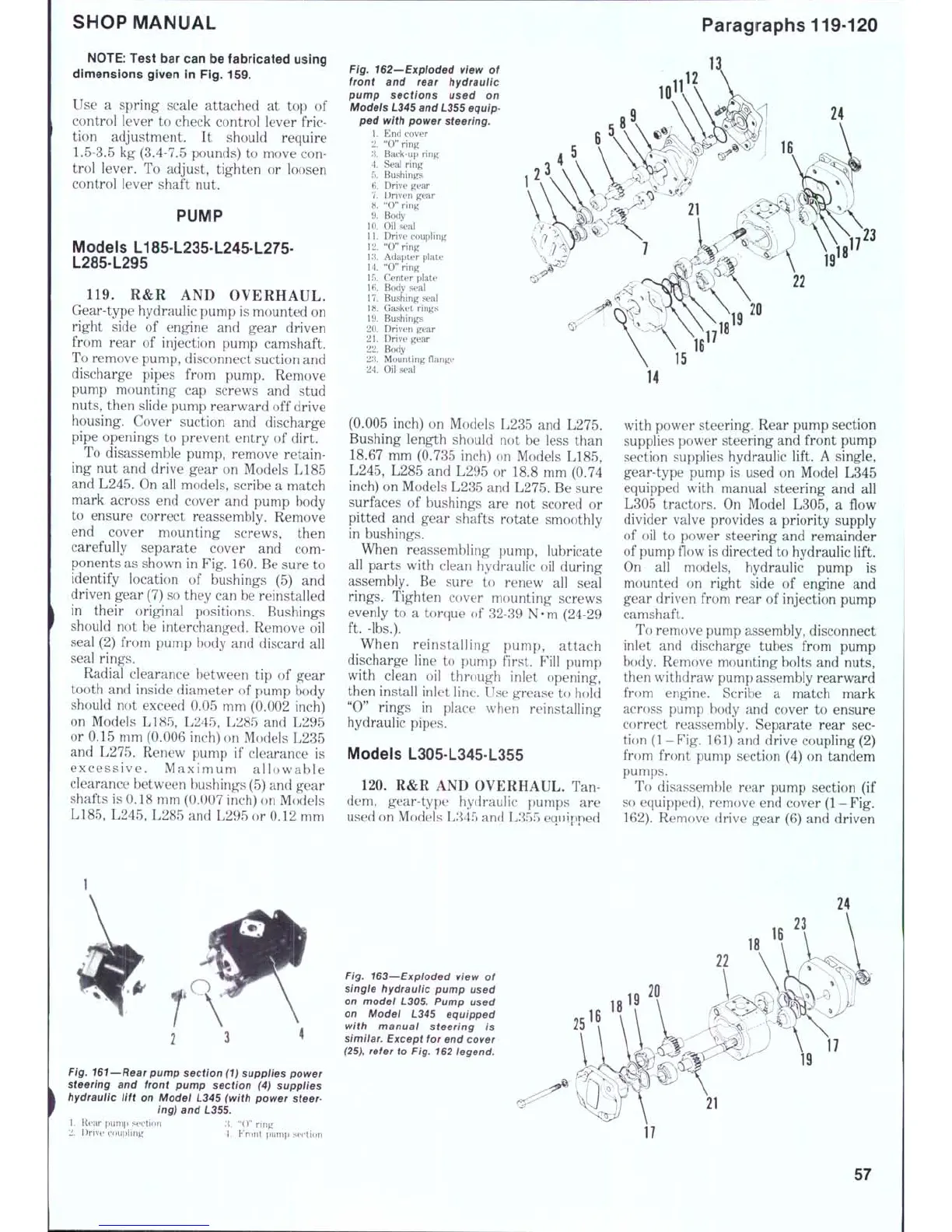
Fig. 162'-Exploded view of
front and rear hydraulic
pump sections used on
Modeis L345 and L355 equip-
ped with power steering.
1.
End cover
2.
"0" ring
;i.
Back-up ring
4.
Seal ring
5.
Bushings
6. Drive gear
7.
Driven gear
8. "0" ring
9. Body
10.
Oil seal
11.
Drive coupling
12.
"O"ring
13.
Adapter plate
14.
"0" ring
15.
Center plate
Ifi.
Body seal
17.
Bushing seal
18.
Gasket rings
19.
Bushings
20.
Driven gear
21.
Drive gear
22.
Body
23.
Mounting flange
24.
Oil seal
(0.005 inch) on Models L235 and L275.
Bushing length should not be less than
18.67 mm (0.735 inch) on Models L185,
L245,
L285 and L295 or 18.8 mm (0.74
inch) on Models L235 and L275. Be sure
surfaces of bushings are not scored or
pitted and gear shafts rotate smoothly
in bushings.
When reassembling pump, lubricate
all parts with clean hydraulic oil during
assembly. Be sure to renew all seal
rings.
Tighten cover mounting screws
evenly to a torque of 32-39 N-m (24-29
ft. -lbs.).
When reinstalling pump, attach
discharge line to pump first. Fill pump
with clean oil through inlet opening,
then install inlet line. Use grease to hold
"0"
rings in place when reinstalling
hydraulic pipes.
Models L305 L345 L355
120.
R&R AND OVERHAUL. Tan
dem, gear-type hydraulic pumps are
used on Models L845 and L355 eaninned
i12
24
with power steering. Rear pump section
supplies power steering and front pump
section supplies hydraulic lift. A single,
gear-type pump is used on Model L345
equipped with manual steering and all
L305 tractors. On Model L305, a flow
divider valve provides a priority supply
of oil to power steering and remainder
of pump flow is directed to hydraulic lift.
On all models, hydraulic pump is
mounted on right side of engine and
gear driven from rear of injection pump
camshaft.
To remove pump assembly, disconnect
inlet and divscharge tubes from pump
body. Remove mounting bolts and nuts,
then withdraw pump assembly rearward
from engine. Scribe a match mark
across pump body and cover to ensure
correct reassembly. Separate rear sec-
tion (1-Fig. 161) and drive coupling (2)
from front pump section (4) on tandem
pumps.
To disassemble rear pump section (if
so equipped), remove end cover (1-Fig.
162).
Remove drive gear (6) and driven
Fig. 161—Rear pump section (1) suppiies power
steering and front pump section (4) supplies
hydraulic lift on Model L345 (with power
steer-
ing) and L355.
1.
Rear fiunip section ;}. "()" ring
2.
Drivi" coupling 1. Front pump strtion
Fig. 163~Expioded view of
singie hydrauiic pump used
on model L305. Pump used
on Model L345 equipped
with manual steering is
simiiar.
Except for end cover
(25),
refer to Fig. 162 legend.
19
17
57

 Loading...


