Paragraphs 13-14 KUBOTA
match marks when reinstalling pitman
arm. Refill unit with approximately 0.2
L (% pint) of SAE 90 gear oil.
Reinstall steering unit on tractor and
adjust steering wheel free play as
previously outlined.
POWER STEERING
Integral Type
13.
ADJUSTMENT. Steering wheel
free play should be within range of 25-50
mm (13/16-2 inches) measured at steer-
ing wheel rim. To adjust free play, turn
adjusting screw
(1
-
Fig.
26) clockwise to
reduce free play or counter-clockwise to
increase free play.
To check and adjust relief valve
pressure setting, connect a 0-20000 kPa
(0-3000 psi) pressure gage at test port
(2-Fig. 27) in steering valve housing.
Operate steering until oil is at operating
temperature. With engine running at
2600 rpm, turn and hold steering wheel
fully in one direction and observe
pressure reading when relief valve is ac-
tuated. Pressure should be 10000-10700
kPa (1450-1550 psi) on all models. To ad-
just relief valve pressure setting, turn
adjuster (1) to obtain desired opening
pressure.
If unable to obtain recommended
pressure, check hydraulic pump output
as outlined in paragraph 19. If pump
output is satisfactory, remove and in-
spect relief valve poppet and spring
(33-Fig.28).
14.
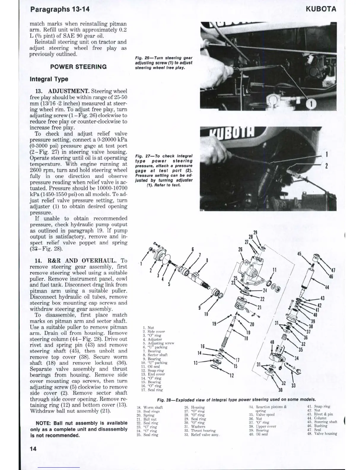
R&R AND OVERHAUL. To
remove steering gear assembly, first
remove steering wheel using a suitable
puller. Remove instrument panel, cowl
and fuel tank. Disconnect drag link from
pitman arm using a suitable puller.
Disconnect hydraulic oil tubes, remove
steering box mounting cap screws and
withdraw steering gear assembly.
To disassemble, first place match
marks on pitman arm and sector shaft.
Use a suitable puller to remove pitman
arm. Drain oil from housing. Remove
steering column
(44
-
Fig.
28). Drive out
rivet and spring pin (43) and remove
steering shaft (45), then unbolt and
remove top cover (38). Secure worm
shaft (18) and remove locknut (36).
Separate valve assembly and thrust
bearings from housing. Remove side
cover mounting cap screws, then turn
adjusting screw (5) clockwise to remove
side cover (2). Remove sector shaft
through side cover opening. Remove re-
taining ring (12) and bottom cover (13).
Withdraw ball nut assembly (21).
NOTE:
Ball nut assembly is available
only as a complete unit and disassembly
Is not recommended.
Fig. 26—Turn steering gear
adjusting screw (1) to adjust
steering wheel free
play.
Fig. 27—To check integral
type power steering
pressure, attach a pressure
gage at test port (2).
Pressure setting can be ad-
justed by turning adjuster
(1).
Refer to text
1.
Nut
2.
Side cover
3.
"0" ring
4.
Adjuster
5.
Adjusting screw
6. "U" packing
7.
Bearing
8. Sector shaft
9. Bearing
10.
"U" packing
11.
Oil seal
12.
Snap ring
13.
End cover
14.
"0" ring
15.
Bearing
16.
"0" ring
17.
Seal ring
14
13-
'^^
12
33
Ftg. 28—Exploded view of Integral type power steering used on some models.
18.
Worm shaft
19.
Seal rings
20.
Spring
21.
Ball nut
22.
Seal ring
23.
" 0 " ring
24.
" 0 " ring
25.
Seal ring
26.
Housing
27.
" 0 " ring
28.
"O" ring
29.
Seal ring
30.
" 0 " ring
31.
Washers
32.
Thrust bearing
33.
Relief valve assy.
;{4.
Reaction pistons
<!
spring
35.
Valve spool
36.
Nut
37.
" 0" ring
38.
Upper cover
39.
Bearing
40.
Oil seal
41.
Snap ring
42.
Nut
43.
Rivet & pin
44.
Column
45.
Steering shaft
46.
Bushing
47.
Seal
48.
Valve housing
14

 Loading...


