Paragraph 7 Cont.
KUBOTA
34
Fig. lO—Bxploded view of outer drive assembiy used on tractors equipped with front-wheel
drive. Some modeis have a spacer between bearing (6) and bevel gear (7) and retain gear with a cap
screw and washer Instead of snap rings (5 and 11).
1.
Axle housing
2.
"0" ring
3.
Shim
4.
Differential yoke shaft
5.
Snap ring
6. Bearing
7.
Bevel gear
8. Bearing
9. Split ring
10.
Bevel gear housing
11.
Snap ring
12.
Bevel gear
13.
Bevel gear shaft
14.
Bearing
15.
Snap ring
16.
Sleeve
17.
Oil seal
18.
Snap ring
19.
Bearing
20.
Shim
21.
Bearing
22.
Bearing cap
23.
Bevel gear
24.
Axle case
25.
Bearing
26.
27.
28.
29.
30.
31.
32.
33.
M.
Bevel gear
Retainer
Retaining ring
Thrust washer
Bearing
Oil seal
"0"
ring
Flange
Axle shaft
11
Pfg.
t t ~ W e i ¥ of front-wheel drive steering linkage and knuckle pins.
1.
Drag link
2.
Arms
3.
Knuckle support R.H.
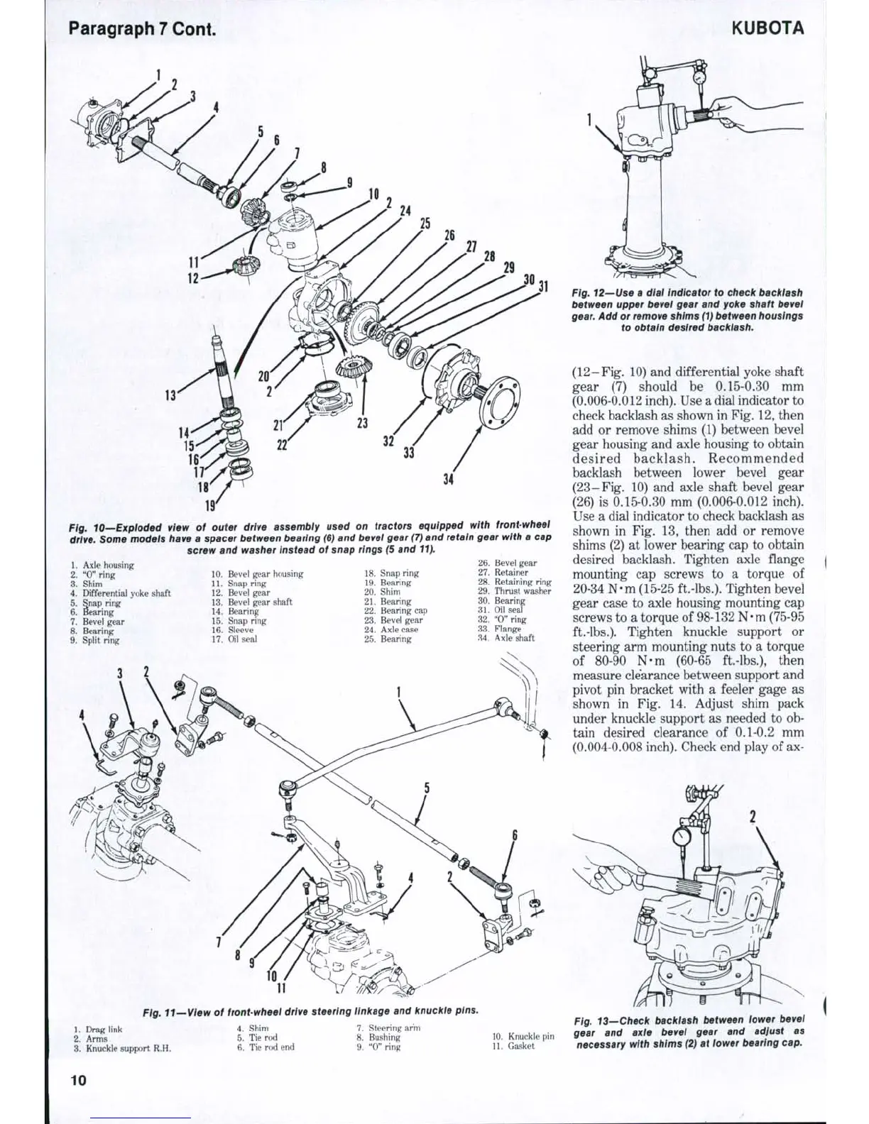
Fig. 12—Use a dial indicator to check backiash
between upper bevel gear and yoke shaft bevei
gear.
Add or remove shims (1) between housings
to obtain desired backlash.
(12-Fig. 10) and differential yoke shaft
gear (7) should be 0.15-0.30 mm
(0.006-0.012 inch). Use a dial indicator to
check backlash as shown in Fig. 12, then
add or remove shims (1) between bevel
gear housing and axle housing to obtain
desired backlash. Recommended
backlash between lower bevel gear
(23-Fig. 10) and axle shaft bevel gear
(26) is 0.15-0.30 mm (0.006-0.012 inch).
Use a dial indicator to check backlash as
shown in Fig. 13, then add or remove
shims (2) at lower bearing cap to obtain
desired backlash. Tighten axle flange
mounting cap screws to a torque of
20-34 N-m (15-25 ft.-lbs.). Tighten bevel
gear case to axle housing mounting cap
screws to a torque of 98-132 N-m (75-95
ft.-lbs.).
Tighten knuckle support or
steering arm mounting nuts to a torque
of 80-90 N-m (60-65 ft.-lbs.), then
measure clearance between support and
pivot pin bracket with a feeler gage as
shown in Fig. 14. Adjust shim pack
under knuckle support as needed to ob-
tain desired clearance of 0.1-0.2 mm
(0.004-0.008 inch). Check end play of ax-
4.
Shim
5.
Tie rod
6. Tie rod end
7.
Steering arm
8. Bushing
9. "0" ring
10.
Knuckle pin
11.
Gasket
Fig. 13—Check backlash between iower bevel
gear and axle bevei gear and adjust as
necessary with shims (2) at lower bearing cap.
10

 Loading...


