Paragraphs 113-115
<?rx\
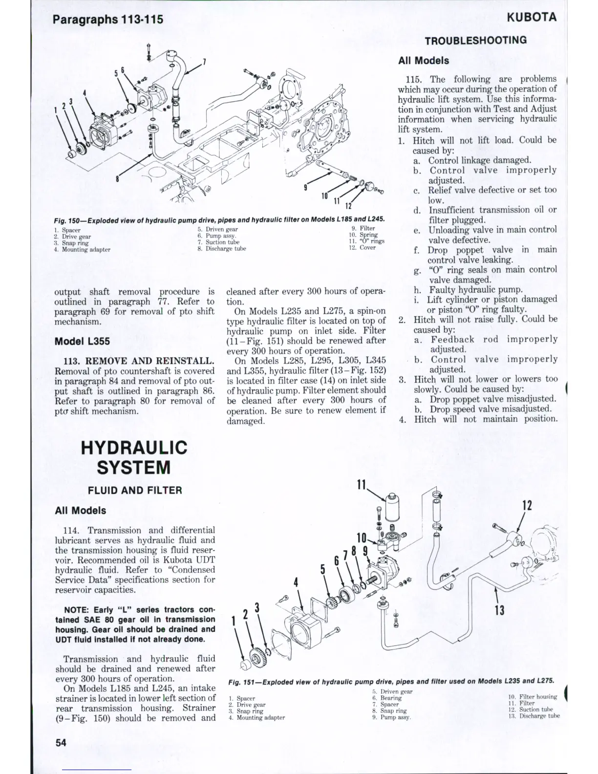
g, 150—Exploded view of hydraulic pump
drive,
pipes and hydraulic fitter on Modeis L185 and L245.
1.
Spacer
2.
Chnve gear
.*i.
Snap ring
4.
Mounting adapter
5.
Driven gear
6. Pump assy.
7.
Suction tube
8. Discharge tube
9. Filter
10.
Spring
11.
"0" ring
12.
Cover
output shaft removal procedure
is
outlined
in
paragraph
77.
Refer
to
paragraph
69 for
removal
of pto
shift
mechanism.
Model L355
113.
REMOVE AND REINSTALL.
Removal
of
pto countershaft
is
covered
in paragraph 84 and removal of pto out-
put shaft
is
outlined
in
paragraph
86.
Refer
to
paragraph
80 for
removal
of
ptcf shift mechanism.
cleaned after every 300 hours
of
opera-
tion.
On Models L235
and
L275,
a
spin-on
type hydraulic filter
is
located
on
top of
hydraulic pump
on
inlet side. Filter
(11-Fig. 151) should
be
renewed after
every 300 hours
of
operation.
On Models L285, L295, L305, L345
and L355, hydraulic filter (13-Fig. 152)
is located
in
filter case (14) on inlet side
of hydraulic pump. Filter element should
be cleaned after every
300
hours
of
operation.
Be
sure
to
renew element
if
damaged.
KUBOTA
TROUBLESHOOTING
All Models
115.
The
following
are
problems
which may occur during the operation of
hydraulic lift system. Use this informa-
tion in conjunction with Test and Adjust
information when servicing hydraulic
lift system.
1.
Hitch will
not
lift load. Could
be
caused
by:
a. Control linkage damaged.
b.
Control valve improperly
adjusted.
c. Relief valve defective
or set too
low.
d. Insufficient transmission
oil or
filter plugged.
e. Unloading valve
in
main control
valve defective.
f.
Drop poppet valve
in
main
control valve leaking.
g.
"0"
ring seals
on
main control
valve damaged.
h. Faulty hydraulic pump,
i. Lift cylinder
or
piston damaged
or piston "0" ring faulty.
2.
Hitch will
not
raise fully. Could
be
caused
by:
a. Feedback
rod
improperly
adjusted.
b.
Control valve improperly
adjusted.
3.
Hitch will
not
lower
or
lowers
too
slowly. Could
be
caused
by:
a. Drop poppet valve misadjusted.
b.
Drop speed valve misadjusted.
4.
Hitch will
not
maintain position.
HYDRAULIC
SYSTEM
FLUID AND FILTER
All Models
114.
Transmission
and
differential
lubricant serves
as
hydraulic fluid
and
the transmission housing
is
fluid reser-
voir. Recommended
oil is
Kubota UDT
hydraulic fluid. Refer
to
"Condensed
Service Data" specifications section
for
reservoir capacities.
NOTE:
Early "L" series tractors con-
tained SAE 80 gear oii in transmission
housing.
Gear oii shouid be drained and
UDT fluid instaiied if not aiready done.
Transmission
and
hydraulic fiuid
should
be
drained
and
renewed after
every 300 hours
of
operation.
On Models L185
and
L245,
an
intake
strainer is located in lower left section of
rear transmission housing. Strainer
(9-Fig.
150)
should
be
removed
and
12
Pig, 151—Expioded view
of
hydraulic pump drive, pipes and fliter used on Models L235 and L275.
1.
Spacer
2.
Drive gear
.'J.
Snap ring
4.
Mounting adapter
5.
Driven gear
6. Bearing
7.
Spacer
8. Snap ring
9. Pump assy.
10.
Filter housing
11.
Filter
12.
Suction tube
i;i. Discharge tube
54

 Loading...


