SHOP MANUAL
allowable clearance is 0.10 mm (0.0039
inch).
Recommended finished inside
diameter of valve guides is 8.015-8.030
mm (0.3156-0.3161 inch).
VALVE SPRINGS
All Models
27.
Valve springs are inter-
changeable for intake and exhaust
valves. Approximate free length is 42
mm (1.65 inches) and minimum
allowable free length is 41.2 mm (1.62 in-
ches) on all models. Renew springs
which are distorted, heat discolored or
fail to meet following test specifications:
Springs should test 117.7 N (26.5
pounds) when compressed to a length of
35.15 mm (1.384 inches). Minimum test
specifications are 100 N (22.5 pounds) at
35.15 mm (1.384 inches).
VALVE LEVERS
All Models
28.
Intake and exhaust valve levers
(rocker arms) are interchangeable on all
models. However, it is recommended
that valve levers be reinstalled in their
original positions if not being renewed.
All valve levers are equipped with
renewable bushings (10-Fig. 48). When
installing new bushing, be sure hole in
bushing is aligned with corresponding
hole in valve lever. Recommended
operating clearance of shaft in valve
levers is 0.02-0.07 mm (0.0008-0.0028
inch) and allowable limit is 0.15 mm
(0.006 inch). Shaft diameter should be
13.973-13.984 mm (0.5501-0.5506 inch)
and bushing inside diameter should be
14.002-14.043 mm (0.5513-0.5529 inch).
Valve levers and shaft are lubricated
by oil metered to shaft support bracket
from rear camshaft bearing. When
assembling valve lever assembly, make
sure all oil passages are open and pro-
perly positioned.
CAM FOLLOWERS
All Models
29.
All models are equipped with bar-
rel type cam followers (tappets) which
can be removed from the top after
removing cylinder head. Cam followers
operate directly in unbushed crankcase
bores on all models.
Check for wear or other damage and
renew if necessary. Check camshaft at
same time and renew if cam lobe surface
is chipped, scored or excessively worn.
Refer to paragraph 33.
VALVE TIMING
All Models
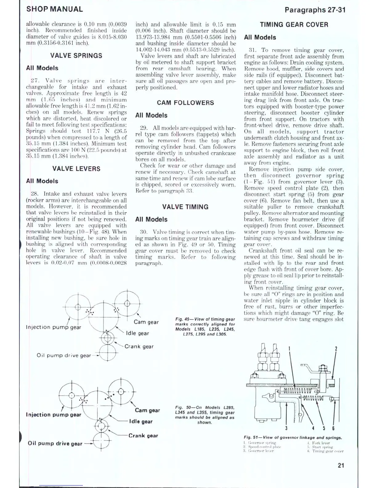
30.
Valve timing is correct when tim-
ing marks on timing gear train are align-
ed as shown in Fig. 49 or 50. Timing
gear cover must he removed to check
timing marks. Refer to following
paragraph.
Injection punnp gear
Oil punnp drive gear
Idle gear
Crank gear
Fig. 49—View of timing gear
marks correctly aligned for
Modeis L185, 1235, L245,
L275, L295 and L305.
Injection pump gear
Oil pump drive gear
Cam gear
Idle gear
Crank gear
Fig. 50—On Modeis L285,
L345 and L355, timing gear
marks shouid be aiigned as
shown.
Paragraphs 27-31
TIMING GEAR COVER
All Models
31.
To remove timing gear cover,
first separate front axle assembly from
engine as follows: Drain cooling system.
Remove hood, muffler, side covers and
side rails (if equipped). Disconnect bat-
tery cables and remove battery. Discon-
nect upper and lower radiator hoses and
intake manifold hose. Disconnect steer-
ing drag link from front axle. On trac-
tors equipped with booster-type power
steering, disconnect booster cylinder
from front support. On tractors with
front-wheel drive, remove drive shaft.
On all models, support tractor
underneath clutch housing and front ax-
le.
Remove fasteners securing front axle
support to engine block, then roll front
axle assembly and radiator as a unit
away from engine.
Remove injection pump side cover,
then disconnect governor spring
(1-Fig. 51) from governor lever (3).
Remove speed control plate (2), then
disconnect start spring (5) from gear
cover (6). Remove fan belt, then use a
suitable puller to remove crankshaft
pulley. Remove alternator and mounting
bracket. Remove hourmeter drive (if
equipped) from front cover. Disconnect
water pump by-pass hose. Remove re-
taining cap screws and withdraw timing
gear cover.
Crankshaft front oil seal can be re-
newed at this time. Seal should be in-
stalled with lip to the rear and front
edge fiush with front of cover bore. Ap-
ply grease to oil seal lip prior to reinstall-
ing^ front cover.
When reinstalling timing gear cover,
be sure all "0" rings are in position and
water inlet nipple in cylinder block is
free of rust, burrs or other imperfec-
tions which might damage "0" ring. Be
sure hourmeter drive tang engages slot
^
"V^.
//j////////./yy//////////Z<W//C^i^yy^y/7/A^A
Mm
3
4 5 6
Fig. 51—View of governor linkage and springs.
1.
(lovernor sp
\. Fork Ifver
f).
Start spring
(i.
Timing gear cover
21

 Loading...


