SHOP MANUAL
Pararaphs 94-99
1
Fig. 129—Position set coliars (1) and snap rings
(2)
as shown when reinstaiiing differentiai pinion
shafts (3) on Modeis
L2B5,
L305, L345 and L355.
cover. Align match marks on side and pi-
nion gears made prior to disassembly.
Position set collars (1-Fig. 129) and
snap rings (2) as shown. Tighten bevel
ring gear mounting bolts to a torque of
61-70 N-m (45-50 ft. -lbs.) Be sure
lockplates
(1
-
Fig.
128) cover dowel pins
(2).
All Models
94.
BEARING PRELOAD. To
check differential bearing preload,
measure torque required to rotate bevel
pinion shaft and differential assembly
using a torque wrench as shown in Fig.
130.
Rotating torque should be 0.4-0.9
N-m (4-8 in.-lbs.) on Models L185, L245
and L285;
1.4-4.1
N-m (13-36 in.-lbs.) on
Model L235; 3.9-6.4 N-m (35-66 in.-lbs.)
on Model L275; 0.9-1.1 N-m (8-10
in.-lbs.) on Models L295, L305, L345 and
L355.
Adjust preload by changing
thickness of differential carrier bearing
shims until desired rotating torque is ob-
tained.
95.
BACKLASH ADJUSTMENT.
Backlash between bevel pinion gear and
bevel ring gear should be 0.20-0.25 mm
(0.008-0.010 inch). To check backlash,
position a dial indicator against tip of
one ring gear tooth (Fig. 131). Secure pi-
nion shaft, move ring gear by hand and
Fig. 131—Use diai indicator to check backiash
between bevei ring gear and pinion
gear.
note dial indicator reading.
If backlash is too large, remove bear-
ing case shims from ring gear side and
install removed shims on opposite side.
If backlash is too small, remove shims
from differential case side and install
removed shims on opposite side.
NOTE:
Do not change total shim pack
thickness as bearing preioad adjustment
would be affected.
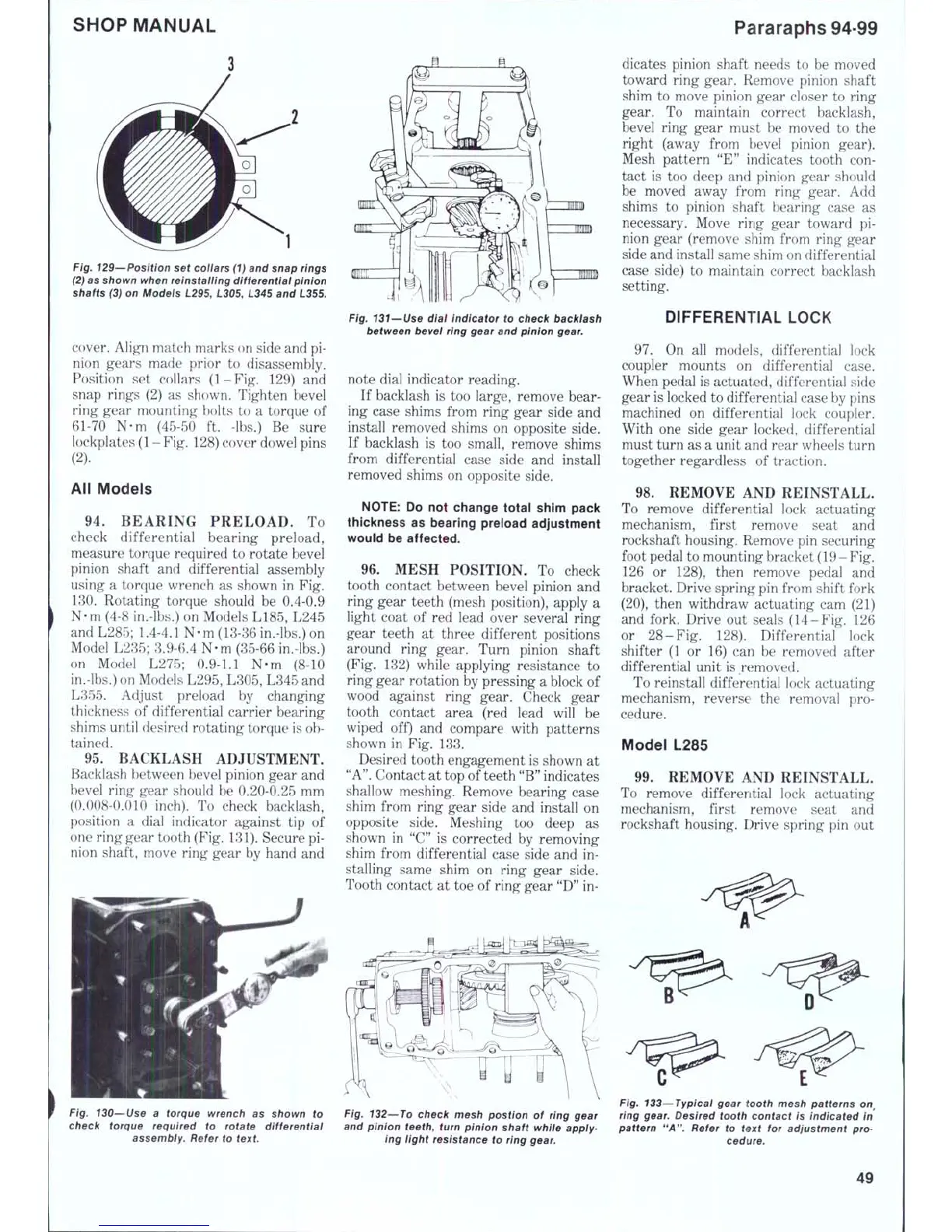
96.
MESH POSITION. To check
tooth contact between bevel pinion and
ring gear teeth (mesh position), apply a
light coat of red lead over several ring
gear teeth at three different positions
around ring gear. Turn pinion shaft
(Fig. 132) while applying resistance to
ring gear rotation by pressing a block of
wood against ring gear. Check gear
tooth contact area (red lead will be
wiped off) and compare with patterns
shown in Fig. 133.
Desired tooth engagement is shown at
"A".
Contact at top of teeth
"B"
indicates
shallow meshing. Remove bearing case
shim from ring gear side and install on
opposite side. Meshing too deep as
shown in "C" is corrected by removing
shim from differential case side and in-
stalling same shim on ring gear side.
Tooth contact at toe of ring gear
"D"
in-
dicates pinion shaft needs to be moved
toward ring gear. Remove pinion shaft
shim to move pinion gear closer to ring
gear. To maintain correct backlash,
bevel ring gear must be moved to the
right (away from bevel pinion gear).
Mesh pattern "E" indicates tooth con-
tact is too deep and pinion gear should
be moved away from ring gear. Add
shims to pinion shaft bearing case as
necessary. Move ring gear toward pi-
nion gear (remove shim from ring gear
side and install same shim on differential
case side) to maintain correct backlash
setting.
DIFFERENTIAL LOCK
97.
On all models, differential lock
coupler mounts on differential case.
When pedal is actuated, differential side
gear is locked to differential case by pins
machined on differential lock coupler.
With one side gear locked, differential
must turn as a unit and rear wheels turn
together regardless of traction.
98.
REMOVE AND REINSTALL.
To remove differential lock actuating
mechanism, first remove seat and
rockshaft housing. Remove pin securing
foot pedal to mounting bracket (19- Fig.
126 or 128), then remove pedal and
bracket. Drive spring pin from shift fork
(20),
then withdraw actuating cam (21)
and fork. Drive out seals (14-Fig. 126
or 28-Fig. 128). Differential lock
shifter (1 or 16) can be removed after
differential unit is removed.
To reinstall differential lock actuating
mechanism, revei'se the removal pro-
cedure.
Model L285
99.
REMOVE AND REINSTALL.
To remove differential lock actuating
mechanism, first remove seat and
rockshaft housing. Drive spring pin out
Fig. 130—Use a torque wrench as shown to
check torque required to rotate differentiai
assembiy. Refer to
text.
Fig. 132~To check mesh postion of ring gear
and pinion teeth, turn pinion shaft while appiy-
ing iight resistance to ring
gear.
Fig. 133—Typicai gear tooth mesh patterns
on^
ring
gear.
Desired tooth contact is indicated in
pattern "A". Refer to text for adjustment pro-
cedure.
49

 Loading...


