SHOP MANUAL
Paragraph
7
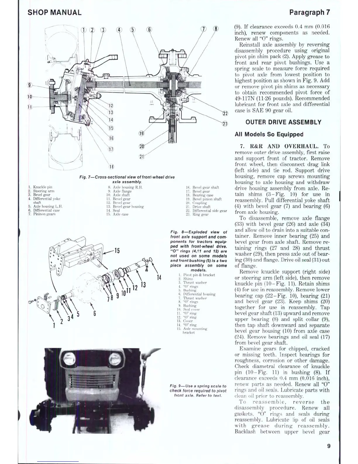
Fig. 7—Cross-sectional view
of
front-wheel
drive
axie assembly.
1. Knuckle
pin 8.
Axle housing
R.H.
2.
Steering arm 9. Axle flange
3.
Bevel gear 10. Axle shaft
4.
Differential yoke 11. Bevel gear
shaft ' 12. Bevel gear
5.
Axle housing L.H. 13. Bevel gear housing
6. Differential ease 14. Seal
7.
Pininon gears 15. Axle case
16.
Bevel gear shaft
17.
Bevel gear
18.
Bearing case
19.
Bevel pinion shaft
20.
Coupling
21.
Drive shaft
22.
Differential side gear
23.
Ring gear
Fig. 8—Expioded view
of
front axte support
and
com-
ponents
for
tractors equip-
ped with front-wheel drive.
"0" rings (4,11
and
12)
are
not used
on
some models
and
front
bushing
(5)
is a two
piece assembly
on
some
models.
1.
Pivot pin & bracket
2.
Shims
3.
Thrust washer
4.
"()" rings
5.
Bushing
6. Differential housing
7.
Thrust washer
8. "(T' rings
9. Bushing
10.
Seal cover
11.
"0" ring
12.
"O"ring
13.
Cover
14.
"0" ring
15.
Axle mounting
bracket
Fig.
9—Use
a
spring scale
to
check force required
to
pivot
front axle. Refer
to
text
(9).
If
clearance exceeds
0.4 mm
(0.016
inch),
renew components
as
needed.
Renew
all
"0" rings.
Reinstall axle assembly
by
reversing
disassembly procedure using original
pivot
pin
shim pack (2). Apply grease
to
front
and
rear pivot bushings.
Use a
spring scale
to
measure force required
to pivot axle from lowest position
to
highest position
as
shown
in
Fig.
9.
Add
or remove pivot
pin
shims
as
necessary
to obtain recommended pivot force
of
49-117N (11-26 pounds). Recommended
lubricant
for
front axle
and
differential
case
is
SAE
90
gear
oil.
OUTER DRIVE ASSEMBLY
All Models
So
Equipped
7.
R&R AND
OVERHAUL,
To
remove outer drive assembly, first raise
and support front
of
tractor. Remove
front wheel, then disconnect drag link
(left side)
and tie rod.
Support drive
housing, remove
cap
screws mounting
housing
to
axle housing
and
withdraw
drive housing assembly from axle.
Re-
tain shims (3-Fig.
10) for use in
reassembly. Pull differential yoke shaft
(4) with bevel gear
(7) and
bearing
(6)
from axle housing.
To disassemble, remove axle flange
(33) with bevel gear
(26) and
axle
(34)
and allow
oil
to
drain into
a
suitable
con-
tainer. Remove inner bearing
(25) and
bevel gear from axle shaft. Remove
re-
taining rings
(27 nnd 28) and
thrust
washer (29), then press axle
out
of
bear-
ing
(30)
and
flange. Drive oil seal
(31)
out
of flange.
Remove knuckle support (right side)
or steering
arm
(left side), then remove
knuckle
pin
(10-Fig.
11).
Retain shims
(4)
for
use
in
reassembly. Remove lower
bearing
cap
(22-Fig.
10),
bearing
(21)
and bevel gear
(23).
Keep shims
(20)
together
for use In
reassembly.
T'ap
bevel gear shaft
(13)
upward
and
remove
upper bearing
(8) and
split collar
(9),
then
tap
shaft downward
and
separate
bevel gear housing
(10)
from axle case
(24).
Remove bearings
and oil
seal
(17)
from bevel gear shaft.
Examine gears
for
chipped, cracked
or missing teeth. Inspect bearings
for
roughness, corrosion
or
other damage.
Check diametral clearance
of
knuckle
pin (10-Fig.
11) in
bushing
(8). If
clearance exceeds
0.4 mm
(0.016 inch),
renew parts
as
needed. Renew
all "0"
rings
and oil
seals. Lubricate parts with
clean
oil
prior
to
reassembly.
To reassemb le, revers e
the
disassembly procedure. Renew
all
gaskets.
"0"
rings
and
seals during
reassembly. Lubricate
lip of oil
seals
with grease during reassembly.
Backlash between upper bevel gear

 Loading...


