Paragraphs 126-128
6
KUBOTA
15
14
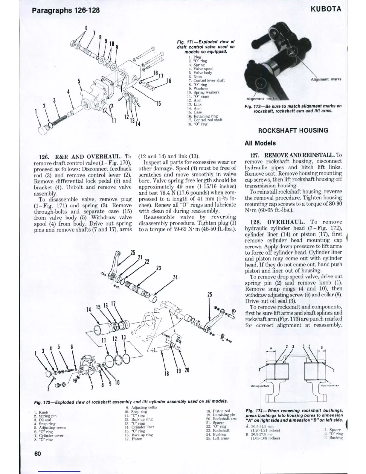
Fig, 171—Exploded view of
draft control valve used on
models so equipped.
1.
Plug
2.
"0" ring
'A. Spring
4.
Valve spool
5.
Valve body
6. Nuts
7.
Control lever shaft
8. "O"ring
9. Washers
10.
Spring washers
11.
"0" rings
12.
Arm
13.
Link
14.
Arm
15.
Case
16.
Retaining ring
17.
Control rod shaft
18.
"0" ring
marks
AHQnnrwnt mark!
Fig. 173—Be sure to match alignment marks on
rockshaft, rockshaft arm and lift arms.
ROCKSHAFT HOUSING
All Models
126.
R&R AND OVERHAUL. To
remove draft control valve
(1
-
Fig.
170),
proceed as follows: Disconnect feedback
rod (3) and remove control lever (2).
Remove differential lock pedal (5) and
bracket (4). Unbolt and remove valve
assembly.
To disassemble valve, remove plug
(1-Fig. 171) and spring (3). Remove
through-bolts and separate case (15)
from valve body (5). Withdraw valve
spool (4) from body. Drive out spring
pins and remove shafts (7 and 17), arms
(12 and 14) and link (13).
Inspect all parts for excessive wear or
other damage. Spool (4) must be free of
scratches and move smoothly in valve
bore.
Valve spring free length should be
approximately 49 mm (1-15/16 inches)
and test 78.4 N (17.6 pounds) when com-
pressed to a length of 41 mm
(1-%
in-
ches).
Renew all "0" rings and lubricate
with clean oil during reassembly.
Reassemble valve by reversing
disassembly procedure. Tighten plug (1)
to a torque of 59-69 N-m (45-50 ft.-lbs.).
25
18
19
20
Fig. 172—Exploded view of rockshaft assembly and lift cylinder assembly used on all models.
1.
Knob
2.
Spring pin
:i.
Oil seal
4.
Snap ring
5.
Adjusting screw
6. "0" ring
7.
Cylinder cover
8. "O" ring
9. Adjusting collar
10.
Snap ring
11.
"O"ring
12.
Back-up ring
Ki.
"0" ring
14.
Cylinder liner
15.
"Oaring
16.
Back-up ring
17.
Piston
18.
Piston rod
19.
Retaining pin
20.
Rockshaft arm
21.
Sp^er
22.
"0" ring
23.
Rockshaft
24.
Bushing
25.
Lift arms
127.
REMOVE AND REINSTALL. To
remove rockshaft housing, disconnect
hydraulic pipes and hitch lift links.
Remove seat. Remove housing mounting
cap
screws,
then lift rockshaft housing off
transmission housing.
To reinstall rockshaft housing, reverse
the removal procedure. Tighten housing
mounting cap screws to a torque of 80-90
N-m (60-65 ft.-lbs.).
128.
OVERHAUL. To remove
hydraulic cylinder head (7-Fig. 172),
cylinder liner (14) or piston (17), first
remove cylinder head mounting cap
screws. Apply down pressure to lift arms
to force off cylinder head. Cylinder liner
and piston may come out with cylinder
head. If they do not come out, hand push
piston and liner out of housing.
To remove drop speed valve, drive out
spring pin (2) and remove knob (1).
Remove snap rings (4 and 10), then
withdraw adjusting screw
(5)
and collar
(9).
Drive out oil seal (3).
To remove rockshaft and components,
first
be
sure lift arms and shaft splines and
rockshaft arm
(Fig.
173)
are punch marked
for correct alignment at reassembly.
2
3 3 2
ing surface
Fig. 174—When renewing rockshaft bushings,
press bushings into housing bores to dimension
"A"
on right side and dimension "B" on left side.
A. 3O..V:il.r) mm
(1.20-1.24 inches)
B.
26,5-27.5 mm
(1.05-1.08 inches)
1.
Spacer
2.
" 0 " ring
3.
Bushing
60

 Loading...


