SHOP MANUAL
Paragraphs 104-106
inward and lubricate seal lip with grease
before reinstalling axle shaft. Differen-
tial gear shaft
and
bull gear must
be
reinstalled
at
the same time. Tighten ax-
le
nut (3) to a
torque
of
196-245
N-m
(145-180 ft.-lbs.), then stake
nut
after
10
11
12
13
14
15
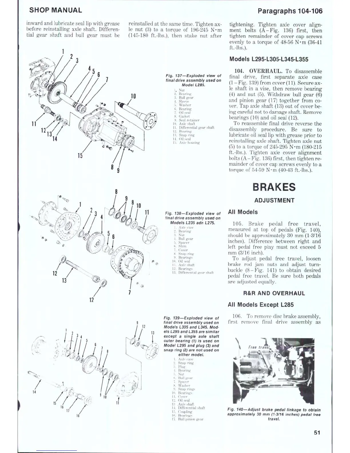
Fig. 137—Exploded view of
final drive assembly used on
1,
2.
;i.
4.
5.
(>.
7.
8.
\l
10.
11.
12.
Ki.
14.
Model L285.
Nut
Bearing
Bull gear
Sleeve
Washer
Bearing
Oil seal
Gasket
Seal retainer
Axle shaft
Differential gear shaft
Bearing
Snap ring
Oil seal
If).
Axle housing
tightening. Tighten axle cover align-
ment bolts (A-Fig.
136)
first, then
tighten remainder
of
cover
cap
screws
evenly
to a
torque
of
48-56 N-m (36-41
ft.-lbs.).
Models L295-L305-L345-L355
104.
OVERHAUL.
To
disassemble
final drive, first separate axle case
(1-Fig. 139) from cover
(11).
Secure ax-
le shaft
in a
vise, then remove bearing
(4)
and nut
(5). Withdraw bull gear
(6)
and pinion gear (17) together from
co-
ver. Tap axle shaft (13) out
of
cover be-
ing careful not to damage shaft. Remove
bearings (10) and oil seal (12).
To reassemble final drive reverse
the
disassembly procedure.
Be
sure
to
lubricate oil seal lip with grease prior
to
reinstalling axle shaft. Tighten axle
nut
(5)
to a
torque
of
245-295 N-m (180-215
ft.-lbs.).
Tighten axle cover alignment
bolts (A-Fig. 136) first, then tighten re-
mainder
of
cover cap screws evenly
to a
torque
of
54-59 N-m (40-43 ft.-lbs.).
10
11
Fig. 138—Exploded view
of
finai drive assembiy used on
Models L235 adn L275.
1.
Axle case
2.
Bearing
:{.
Nut
4.
Bull gear
5.
Spacer
ti.
Shim
7.
("over
H. Snap ring
9. Bearings
I
(t.
Oil
seal
11.
Axle shaft
12.
Bearings
\:\. Differential gear shaft
Fig. 139^Expioded view
of
finai drive assembly used on
Modeis L305 and L345. Mod-
eis L295 and L355 are simiiar
except
a
single axle shaft
outer bearing
(1) is
used
on
Modei L295 and piug (3) and
snap ring (2) are not used on
either model.
1.
Axle case
2.
Sna{) ring
.'5.
Plug
4.
Bearing
r..
Nut
t;. Bull gear
7.
Spacer
8. Washer
9. Snap rings
U).
Bearings
11.
Cover
12.
Oil
seal
i:i Axle shaft
11.
Differential shaft
15.
Coupling
Hi.
Bearings
17.
Bull pinion g(>ar
BRAKES
ADJUSTMENT
All Models
105.
Brake pedal free travel,
measured
at top of
pedals
(Fig. 140),
should
be
approximately
30
mm (1-3/16
inches). Difference between right
and
left pedal free play must
not
exceed
5
mm (3/16 inch).
To adjust pedal free travel, loosen
brake
rod jam
nuts
and
adjust turn-
buckle (8-Fig.
141) to
obtain desired
pedal free travel.
Be
sure both pedals
are adjusted equally.
R&R AND OVERHAUL
All Models Except L285
106.
To remove disc brake assembly,
first remove final drive assembly
as
>
1.
^1.
free trdvei^
Fig. 140—Adjust brake pedal linkage
to
obtain
approximateiy
30
mm (1-3/16 inches) pedal free
tra vei.
51

 Loading...


