Paragraphs 48-52
nuts,
align control rack
pin
with slot
in
crankcase
(Fig. 60) and
lift pump
assembly from crankcase. Do not lose or
damage shim pack located between
pump fiange
and
crankcase. Shims con-
trol pump timing
and
same number
of
shims must be reinstalled unless timing
is
to be
changed.
When reinstalling pump,
be
sure
to
guide rack control
pin
into notch
in
governor
arm and
crankcase.
Use
removed shim pack unless timing is to be
changed. Bleed
air
from system
as
previously outlined.
48.
GOVERNOR LINKAGE
AD-
JUSTMENT. High speed adjustment
screw (2-Fig.
62) and
maximum fuel
limit stop (1
or
lA) should not normally
require adjustment unless governor
or
injection pump
is
overhauled.
Ad-
justments should
be
made
by
qualified
personnel only.
Recommended slow idle speed
is 800
to 850 rpm
for
all models. Adjustment is
made by turning slow idle stop (3). High
idle speed should
be
2550
rpm for
Model L285; 2750
rpm for
Models
L235,
L275 and L355 and 2950 rpm
for
Models
L185,
L245, L295, L305
and
L345.
Turn high idle stop screw (2)
for
adjustment.
49.
GOVERNOR
AND
FUEL
CAMSHAFT. Governor assembly
can
be removed with the drive gear and fuel
camshaft as
a
unit after removing injec-
tion pump, fuel feed pump
(if so
equip-
ped),
timing gear cover
as
outlined
in
paragraph 31,
and
hydraulic pump
and
drive gear from rear
end of
fuel
cam-
13
shaft. Remove governor mounting
cap
screws and withdraw governor and cam-
shaft
as an
assembly.
To disassemble, remove fork pivot
shaft (18-Fig. 62A)
and
separate fork
levers (21
and
22) and fork lever holder
(24).
Remove drive gear retaining ring
(1),
then remove gear
and
weight
assembly
(2
through
8)
using
a
suitable
puller. (Governor weight thrust bearing
(6) contains
39
loose balls.
Be
careful
that none
are
lost when weight unit
is
disassembled.
Examine cupped race (5), balls (4) and
ball travel surface
on
back
of
gear
for
furrowing
or
pitting
and
renew
if
damaged. Inspect fuel camshaft
and
bearings
for
scoring, wear
or
other
damage and renew
as
necessary.
Reassemble
by
reversing
the
disassembly procedure.
Be
sure
hydraulic pump drive gear
is
installed
with hub facing forward. Bleed
air
from
system, check timing and adjust gover-
nor linkage
as
previously outlined.
INJECTOR NOZZLES
WARNING. Fuel leaves injector nozzle
with sufficient force to penetrate the
skin.
When testing, keep exposed portions of
your body clear of nozzle spray and wear
suitable eye protection. Make sure testing
is performed in a well vented area.
All Models
50.
TESTING
AND
LOCATING
FAULTY NOZZLE.
If
engine does
not
run properly
and a
faulty injection noz-
zle
is
suspected, check
for
faulty nozzle
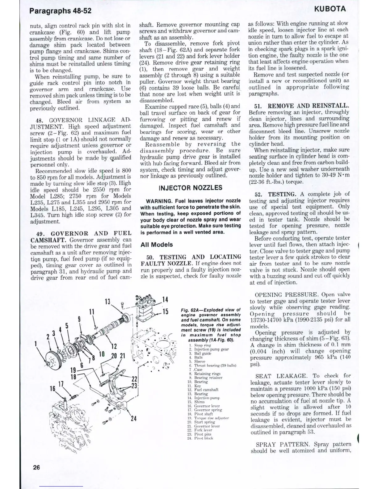
Fig. 62A—Expioded view
of
engine governor assembly
and fuel camshaft. On some
models, torque rise adjust-
ment screw (19)
is
included
In maximum fuel stop
assembly (lA-Flg. 60),
1.
Snap ring
2.
Injection pump gear
3.
Ball guide
4.
Baits
5. Sleeve
6. Thrust bearing (39 balls)
7 .Case
8. Retaining rings
9. Bearing retainer
10.
Bearing
11.
Key
12.
Fuel camshaft
13.
Bearing
14.
Injection pump
15.
Shims
16.
Governor lever
17.
Governor spring
18.
Pivot shaft
19.
Torque rise adjuster
20.
Start spring
21.
Governor lever
22.
Fork !ever
23.
Pivot pins
24.
Pivot block
KUBOTA
as follows: With engine running
at
slow
idle speed, loosen injector line
at
each
nozzle
in
turn
to
allow fuel
to
escape
at
union rather than enter the cylinder.
As
in checking spark plugs
in a
spark igni-
tion engine,
the
faulty nozzle
is the one
that least affects engine operation when
its fuel line
is
loosened.
Remove
and
test suspected nozzle (or
install
a new or
reconditioned unit)
as
outlined
in
appropriate following
paragraphs.
51.
REMOVE AND REINSTALL.
Before removing
an
injector, throughly
clean injector, lines
and
surrounding
area. Remove high pressure fuel line and
disconnect bleed line. Unscrew nozzle
holder from
its
mounting position
on
cylinder head.
When reinstalling injector, make sure
seating surface
in
cylinder head
is
com-
pletely clean and free from carbon build-
up.
Use a new
seal washer underneath
nozzle holder
and
tighten
to
30-49 N*m
(22-36 ft.-lbs.) torque.
52.
TESTING.
A
complete
job of
testing
and
adjusting injector requires
use
of
special test equipment. Only
clean, approved testing oil should be us-
ed
in
tester tank. Nozzle should
be
tested
for
opening pressure, nozzle
leakage
and
spray pattern.
Before conducting test, operate tester
lever until fuel fiows, then attach injec-
tor. Close valve to tester gage and pump
tester lever
a
few quick strokes
to
clear
air from tester
and to be
sure nozzle
valve
is not
stuck. Nozzle should open
with
a
buzzing sound and cut
off
quickly
at end
of
injection.
OPENING PRESSURE. Open valve
to tester gage
and
operate tester lever
slowly while observing gage reading.
Opening pr es su re should
be
13730-14700 kPa (1990-2135 psi)
for all
models.
Opening pressure
is
adjusted
by
changing thickness
of
shim (5-Fig. 63).
A change
in
shim thickness
of
0.1
mm
(0.004 inch) will change opening
pressure approximately
965 kPa (140
psi).
SEAT LEAKAGE.
To
check
for
leakage, actuate tester lever slowly
to
maintain
a
pressure 1000
kPa
(150
psi)
below opening pressure. There should be
no accumulation
of
fuel
at
nozzle tip.
A
slight wetting
is
allowed after
10
seconds
if no
drops
are
formed.
If
fuel
leakage
is
evident, injector must
be
disassembled, cleaned and overhauled
as
outlined
in
paragraph 53.
SPRAY PATTERN. Spray pattern
should
be
well atomized
and
uniform.
26

 Loading...


