Paragraph 89 Cont.
KUBOTA
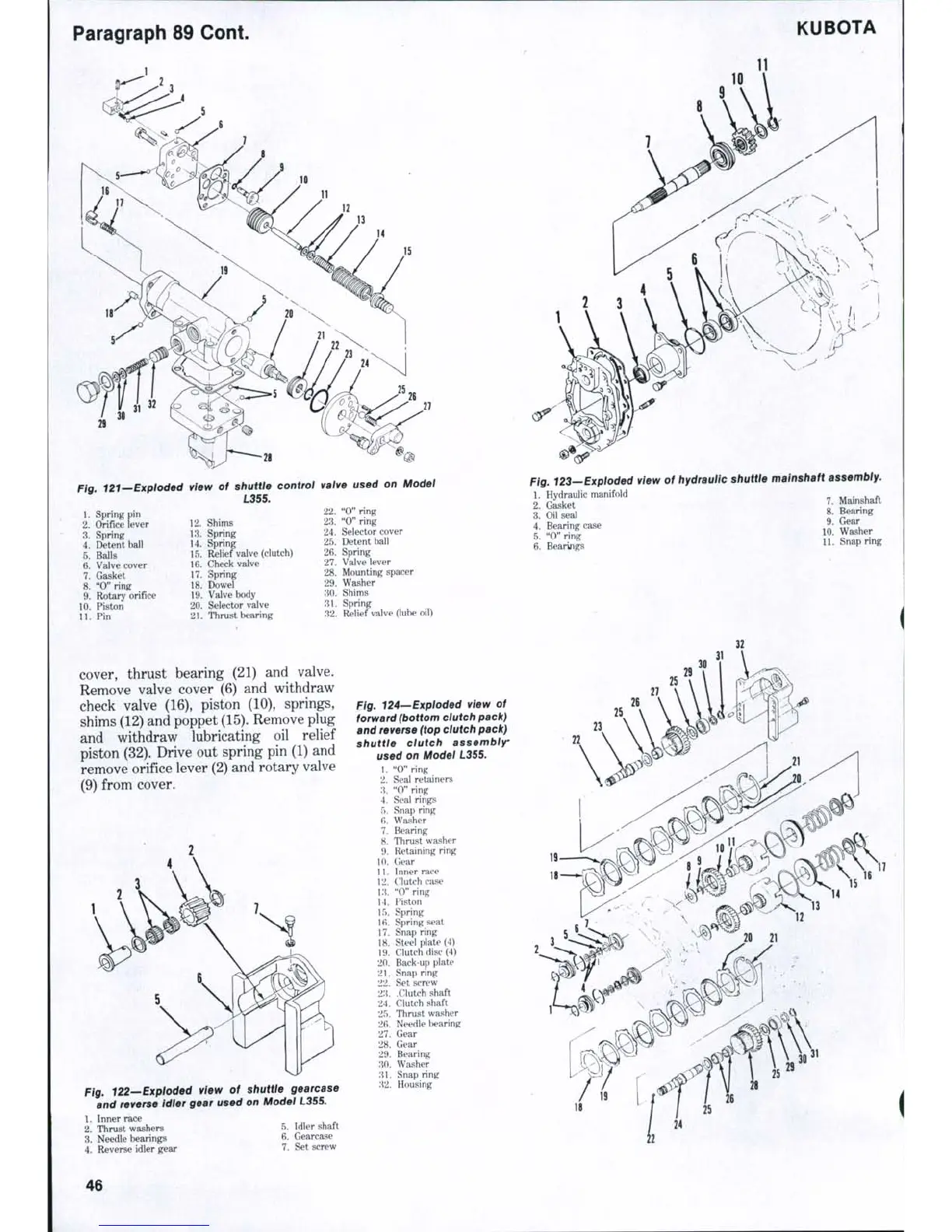
Fig. 121-~Expioded
1.
Spring pin
2.
Orifice lever
3.
Spring
4.
Detent bail
5.
Balls
6. Valve cover
7.
Gasket
8. "0" ring
9. Rotary orifice
10.
Piston
11.
Pin
view of shuttle control
L355.
12.
Shims
13.
Spring
14.
Spring
15.
Relief valve (clutch)
16.
Check valve
17.
Spring
18.
Dowel
19.
Valve body
20.
Selector valve
21.
Thrust bearing
valve used on Model
22.
"0" ring
23.
"0" ring
24.
Selector cover
25.
Detent ball
26.
Spring
27.
Valve lever
28.
Mounting spacer
29.
Washer
30.
Shims
31.
Spring
32.
Relief valve (lube oil)
Fig. 123—Exploded view of hydraulic shuttle mainshaft assembly.
1.
Hydraulic manifold
2.
Gasket
3. Oil seal
4.
Bearing case
5.
"0" ring
6. Bearings
7.
Mainshaft
8. Bearing
9. Gear
10.
Washer
11.
Snap ring
cover, thrust bearing (21) and valve.
Remove valve cover (6) and withdraw
check valve (16), piston (10), springs,
shims (12) and poppet
(15).
Remove plug
and withdraw lubricating oil relief
piston (32). Drive out spring pin (1) and
remove orifice lever (2) and rotary valve
(9) from cover.
Fig. 122—Expioded view of shuttle gearcase
and reverse idier gear used on Modei L355.
fig, 124—Exploded view of
forward (bottom clutch pacJr)
and reverse (top clutch pack)
shuttle dutch assembir
used on Modei L355.
1.
"0" ring
2.
Seal retainers
X "0" ring
4.
Seal rings
5.
Snap ring
fi. Washer
7.
Bearing
8. Thrust washer
9. Retaining ring
10.
Gear
11.
Inner race
12.
Clutch case
13.
"0" ring
14.
Piston
15.
Spring
16.
Spring seat
17.
Snap ring
18.
Steel plate (4)
19.
Clutch disc (4)
20.
Back-up plate
2\.
Snap ring
22.
Set screw
23.
.Clutch shaft
24.
Clutch shaft
25.
Thrust washer
:^6.
Needle l>earing
27.
Gear
28.
Gear
29.
Bearing
30.
Washer
31.
Snap ring
32.
Housing
1.
Inner race
2.
Thrust washers
3.
Needle bearings
4.
Reverse idler gear
5.
Idler shaft
6. Gearcase
7.
Set screw
46

 Loading...


