Paragraphs 40-45
KUBOTA
locating cap screws to 64-68 N*m (47-50
ft.-lbs.).
Lubricate lip of rear oil seal (7)
before reinstalling rear cover over
crankshaft hub. Tighten fiywheei retain-
ing cap screws to a torque of 98-108
N-m (73-80 ft.-lbs.).
CRANKSHAFT
REAR OIL SEAL
All Models
40.
The lip type crankshaft rear oil
seal (7-Fig. 54) is contained in rear
bearing cover and can be renewed after
splitting tractor between engine and
clutch housing as outlined in paragraph
64 and removing clutch and fiywheei.
Install new seal with lip towards inside
and coat seal lip with grease prior to
reassembly. Refer to following
paragraph when reinstalling fiywheei.
FLYWHEEL
All Models
41.
Flywheel is re tained to
crankshaft fiange by six evenly spaced
cap screws and can be installed in any of
six positions. To be sure fiywheei will be
reinstalled correctly, remove one of the
retaining cap screws and spray fiywheei
and exposed cap screw hole witli quick-
drying paint. Then, when reinstalling
fiywheei, make certain paint marks are
in register.
Flywheel ring gear is a shrink fit on
fiywheei. Heat gear evenly prior to in-
stallation, then install with beveled end
of teeth towards front of flywheel.
Inspect pilot bearing and renew if
necessary. Make sure mating surfaces of
fiywheei and crankshaft fiange are clean
and free of dirt, rust or burrs. Tighten
retaining cap screws evenly to a torque
of 98-108 N-m (73-80 ft.-lbs.).
OIL PUMP
All Models
42.
The rotary type engine oil pump
mounts on front of cylinder block and is
driven by crankshaft gear. Pump can be
removed after removing timing gear
cover.
To check engine oil pressure, remove
oil pressure switch and install a pressure
gage (Fig. 55). With engine at operating
temperature, check oil pressure at idle
speed and rated speed. Pressure should
be at least lOOkPa (14 psi) at idle speed
and should be within range of 295-440
kPa (43-60 psi) at rated engine speed.
Oil pump inner rotor to outer rotor
operating clearance (Fig. 56) should be
0.10-0.16 mm (0.004-0.006 inch) and
maximum allowable clearance is 0.20
mm (0.008 inch). Clearance between
body and outer rotor (Fig. 57) should be
0.11-0.19 mm (0.004-0.007 inch) and a
maximum allowable clearance of 0.25
mm (0.010 inch). End clearance between
rotors and cover should not exceed 0.2
Fig. 55—Remove oil pressure switch and Install
pressure gage to check engine oil pressure.
Fig. 56—Maximum atiowabie clearance be-
tween oil pump inner rotor and outer rotor Is 0.20
mm (0.008 inch).
Fig. 57—Clearance between oii pump body and
outer rotor should not exceed 0.25 mm (0.010
Inch).
mm (0.008 inch). Oil pump is available
only as an assembled unit. Renew com-
plete pump if it fails to meet specifica-
tions.
DIESEL FUEL
SYSTEM
43.
All models are equipped with an
inline, multiple plunger type injection
pump, pintle nozzles and glow plugs.
Because of extremely close tolerences
and precise requirements of all diesei
components, it is of utmost importance
that clean fuel and careful maintenance
be practiced at all times. Unless
necessary special tools are available,
service on injectors and injection pump
should be limited ot removal, installation
and exchange of complete assemblies. It
is impossible to re-calibrate an injection
pump or reset an injector without pro-
per specifications, equipment and train-
ing.
FUEL FILTER
All Models
44.
MAINTENANCE. On all
models, filter life depends more on
careful fuel system maintenance than it
does on hours or conditions of operation.
Necessity for careful filling with clean
fuel cannot be over-stressed.
Fuel filter should be renewed after
every 400 hours of operation or once a
year, whichever occurs first. Renew
filter immediately if water contamina-
tion is discovered or a decrease in engine
power is evident. Air must be bled from
system as outlined in following
paragraph after installing new filter.
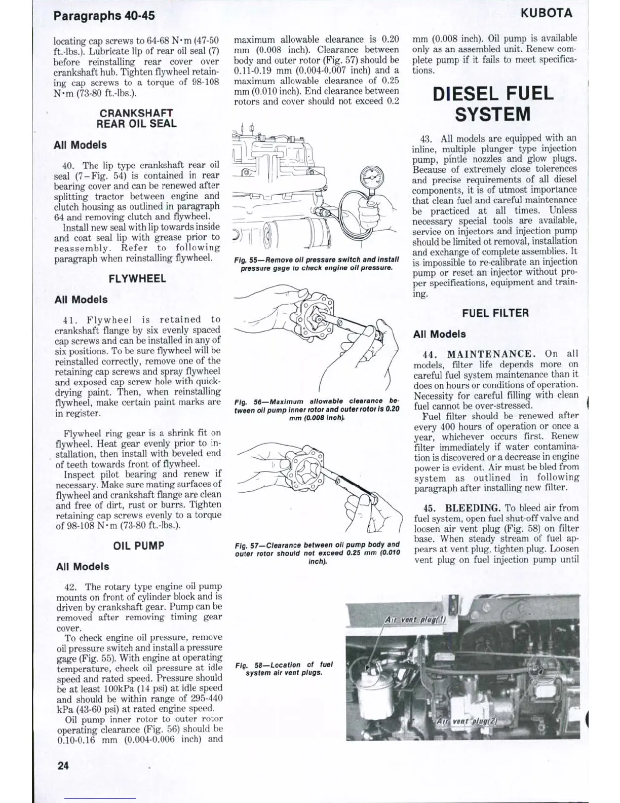
45.
BLEEDING. To bleed air from
fuel system, open fuel shut-off valve and
loosen air vent plug (Fig. 58) on filter
base.
When steady stream of fuel ap-
pears at vent plug, tighten plug. Loosen
vent plug on fuel injection pump until
Fig. 58—Location of fuel
system air vent plugs.
24

 Loading...


