STV32 · STV36 · STV40, WSM ENGINE
1-S57
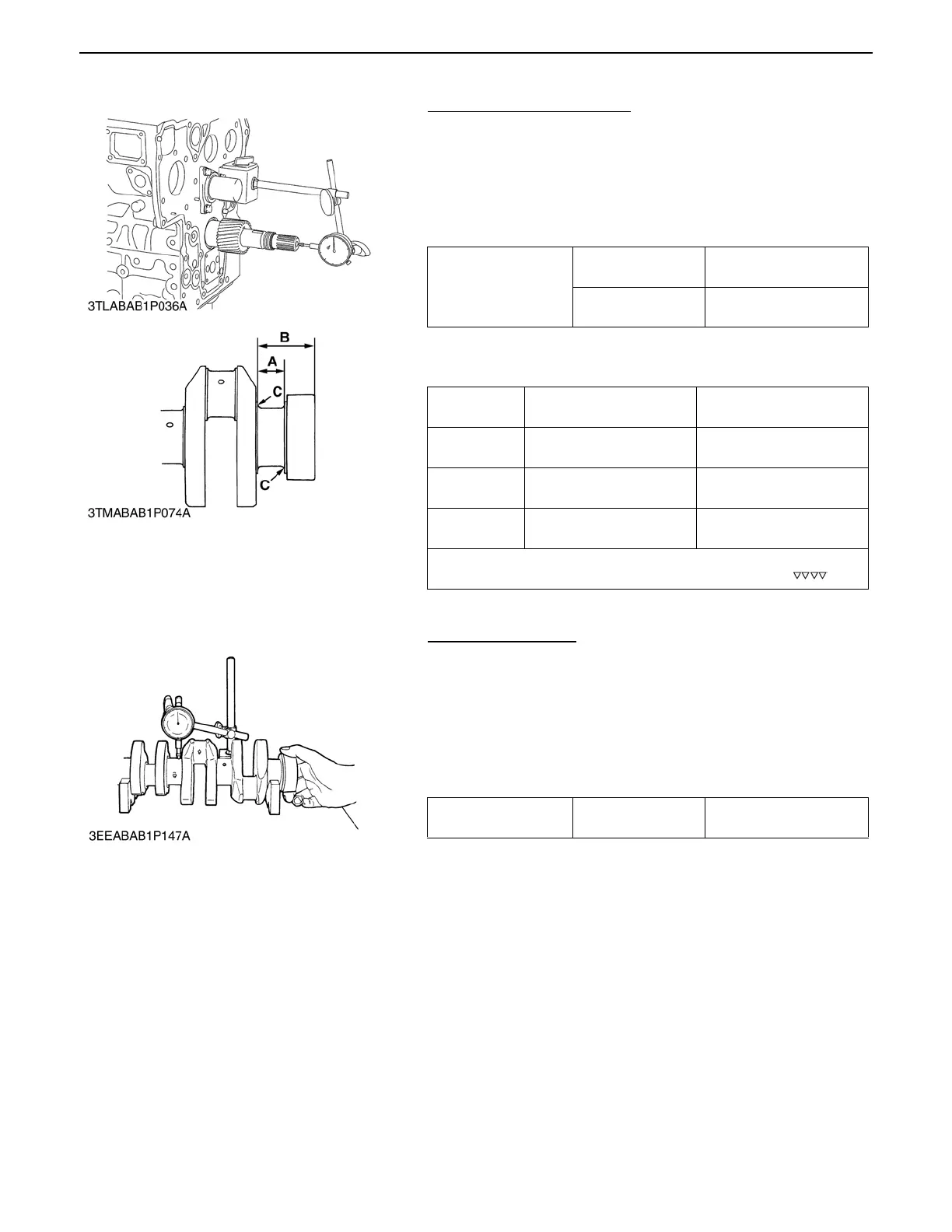
(4) Crankshaft
Side Clearance of Crankshaft
1. Move the crankshaft to the flywheel side.
2. Set a dial indicator to the crankshaft.
3. Measure the end play by pulling the crankshaft toward the
crank gear.
4. If the measurement exceeds the allowable limit, replace the
thrust bearing 1 and 2.
(Reference)
A Oversize dimensions of crankshaft journal
Crankshaft Alignment
1. Support the crankshaft with V blocks on the surface plate and
set a dial indicator with its tip on the intermediate journal at
right angle.
2. Rotate the crankshaft on the V blocks and get the
misalignment (half of the measurement).
3. If the misalignment exceeds the allowable limit, replace the
crankshaft.
Crankshaft side
clearance
Factory spec.
0.15 to 0.31 mm
0.0059 to 0.0122 in.
Allowable limit
0.5 mm
0.0197 in.
Oversize
0.2 mm
0.008 in.
0.4 mm
0.016 in.
Dimension A
26.20 to 26.25 mm
1.0315 to 1.0335 in.
26.40 to 26.45 mm
1.0394 to 1.0413 in.
Dimension B
54.5 to 54.7 mm
2.1456 to 2.1535 in.
54.6 to 54.8 mm
2.1496 to 2.1574 in.
Dimension C
2.8 to 3.2 mm radius
0.1102 to 0.1260 in. radius
2.8 to 3.2 mm radius
0.1102 to 0.1260 in. radius
(0.8-S)
The crankshaft journal must be fine-finished to higher than
0000006460E
Crankshaft alignment Allowable limit
0.02 mm
0.00079 in.
0000005496E
 Loading...

