STV32 · STV36 · STV40, WSM FRONT AXLE
6-S7
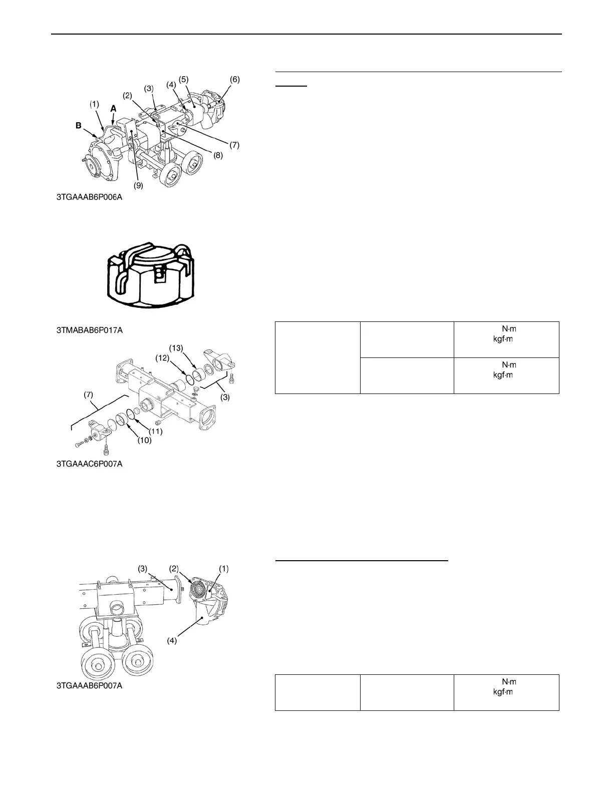
(2) Disassembling Front Axle Assembly
Steering Cylinder, Axle Bracket and Front Wheel Turning Angle
Sensor
1. Remove the slotted nut and remove the both RH and LH tie-
rod (6).
2. Remove the front axle brackets (3), (7).
3. Remove the cylinder cover (5).
4. Remove the hydraulic connector (2) RH or LH to slide out the
steering cylinder (8).
5. Remove the steering cylinder mounting reamer screw (4) and
remove the cylinder (8).
6. Remove the front wheel turning angle sensor (9).
(When reassembling)
A Apply grease to the O-rings (11) (12) and bushings (10) (13)
of front axle bracket.
A After tightening the slotted nut to the specified torque, install
the cotter pin as shown in the figure.
A Apply seal tape to thread portion of hydraulic connector.
A Assemble the sensor arm, longer side (A) fix to the bi-speed
sensor as figure.
Bevel Gear Case and Front Gear Case
1. Remove the bevel gear case mounting screws.
2. Remove the bevel gear case (1) and front gear case (4) as a
unit from the front axle case (3).
(When reassembling)
A Apply grease to the O-ring (2) and take care not to damage it.
A Do not interchange right and left bevel gear case assemblies
and right and left gear case assemblies.
A Be sure to fix the turning angle sensor arm holder.
Tightening torque
Tie-rod end nut (Power
steering cylinder)
34.3 to 44.1
3.5 to 4.5
25.3 to 32.5 ft-lbs
Steering cylinder
mounting reamer screw
48.1 to 55.9
4.9 to 5.7
35.4 to 41.2 ft-lbs
(1) Sensor Arm (10) Bushing
(2) Hydraulic Connector (11) O-ring
(3) Front Axle Bracket (Rear) (12) O-ring
(4) Reamer Screw (13) Bushing
(5) Cylinder Cover
(6) Tie-rod A: Longer Side
(7) Front Axle Bracket (Front) B: Shorter Side
(8) Steering Cylinder
(9) Front Wheel Turning Angle
Sensor
0000007628E
Tightening torque
Bevel gear case
mounting screw
77.5 to 90.2
7.9 to 9.2
57.1 to 66.5 ft-lbs
(1) Bevel Gear Case (3) Front Axle Case
(2) O-ring (4) Front Gear Case