STV32 · STV36 · STV40, WSM ELECTRICAL SYSTEM
9-S8
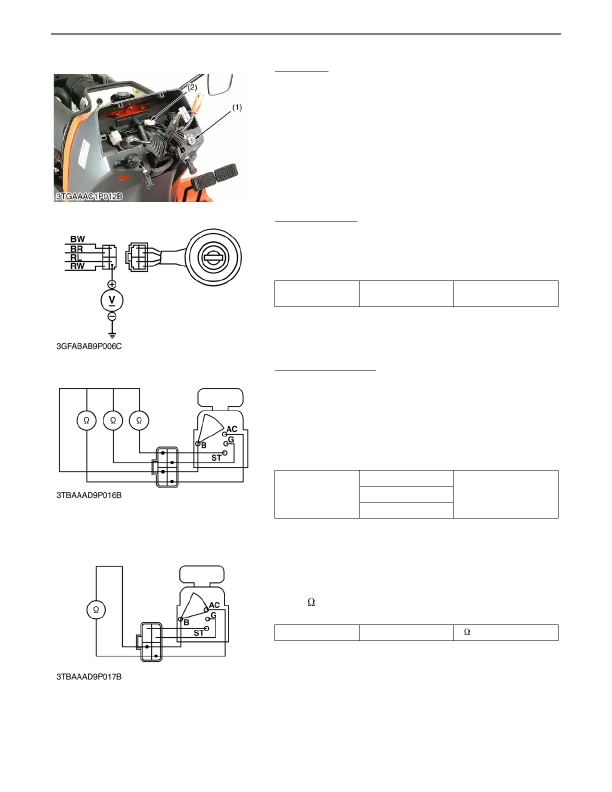
(2) Main Switch
Main Switch
1. Remove the panel board.
2. Disconnect the 4P connector and remove the main switch (1).
3. Perform the following checks.
Connector Voltage
1. Measure the voltage with a voltmeter across the connector B
terminal and chassis.
2. If the voltage differs from the battery voltage (11 to 14 V), the
wiring harness is faulty.
Main Switch Continuity
1) Main Switch Key at OFF Position
1. Set the main switch OFF position.
2. Measure the resistance with an ohmmeter across the B
terminal and the AC terminal, B terminal and ST terminal, B
terminal and G terminal.
3. If infinity is not indicated, the contacts of the main switch are
faulty.
2) Main Switch Key at On Position
1. Set the main switch ON position.
2. Measure the resistance with an ohmmeter across the B
terminal and the AC terminal.
3. If 0 is not indicated, the B - AC contact of the main switch
are faulty.
(1) Main Switch (2) 4P Connector
0000007897E
Voltage
Connector B terminal -
Chassis
Approx. battery voltage
0000008016E
Resistance
B terminal - AC terminal
InfinityB terminal - ST terminal
B terminal - G terminal
0000008017E
Resistance B terminal - AC terminal 0
0000008018E
 Loading...

