STV32 · STV36 · STV40, WSM ELECTRICAL SYSTEM
9-S15
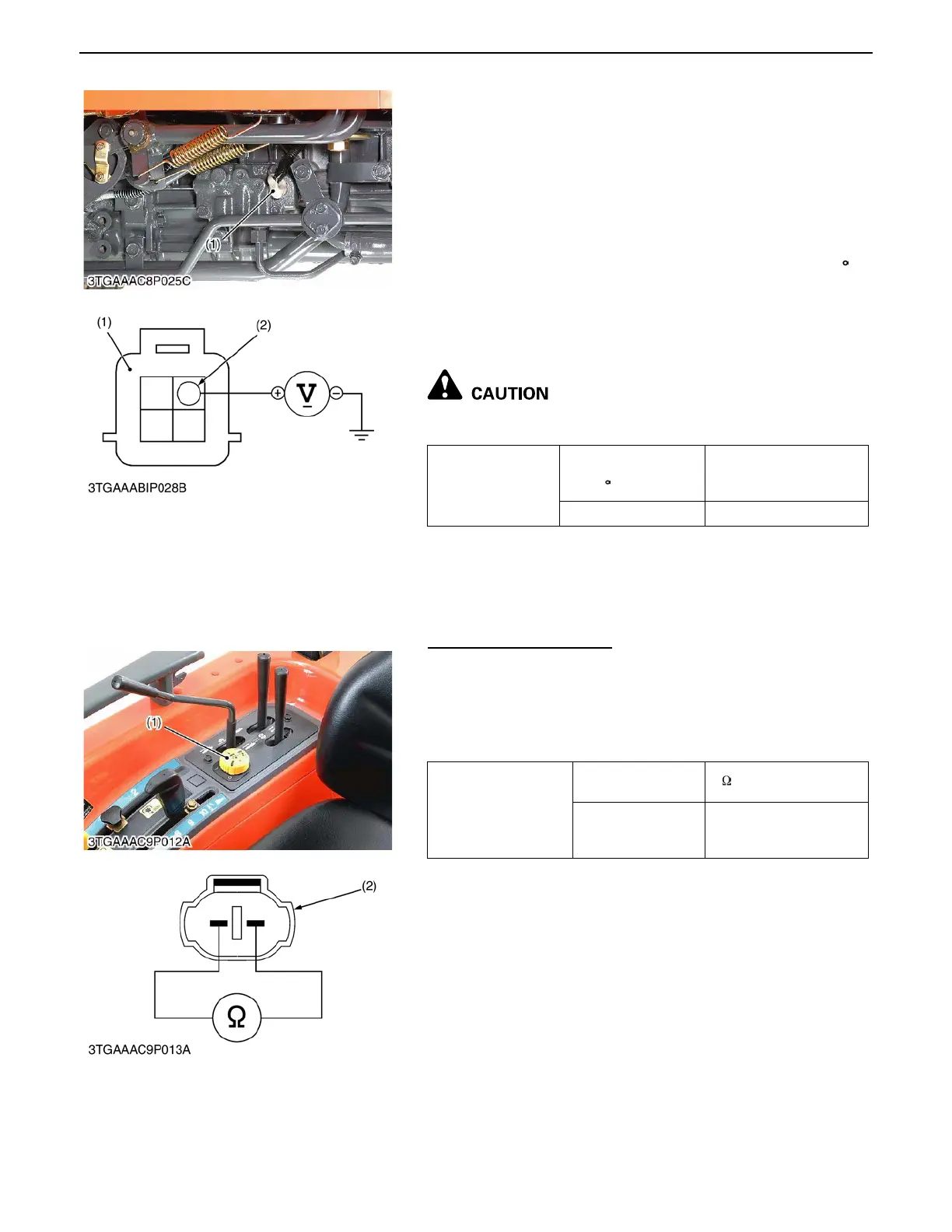
2)Output Voltage
1. Remove the connector for bi-speed valve.
2. Jack up the rear wheels and shift the front wheel drive lever to
OFF position.
3. Start the engine and turn the rear wheels as following
condition.
- Range shift lever : 1
- Cruise control lever : 2 notches
- Engine speed : around 1000 rpm
4. Steer the front wheel to the left or the right 0.61 rad (35 ) or
more.
5. Measure the voltage across the following terminals and
chassis. If the voltage differs from the factory specifications,
check the wire harness.
A Be sure to disengage the front wheel drive, when
checking the voltages with rotate the rear wheel.
(8) PTO Clutch Control Switch
PTO Clutch Control Switch
1. Remove the auxiliary control valve cover.
2. Disconnect the 2P connector (2) of the PTO clutch control
switch (1).
3. Measure the resistance of 2P connector (switch side).
4. If the measurement differs from the table, replace it.
Voltage between
Terminal (2) and
chassis
Front wheel is steered to
the right or the left 0.61
rad (35 ) or more
Battery Voltage
Front wheel is straight OV
(1) Bi-speed Valve Connector (2) Terminal (Y/G)
0000007927E
Resistance
PTO clutch control
switch at ON position
0
PTO clutch control
switch at OFF
position
Resistance Infinity
(1) PTO Clutch Control Switch (2) 2P Connector (Switch Side)
0000007928E
 Loading...

