STV32 · STV36 · STV40, WSM ELECTRICAL SYSTEM
9-S25
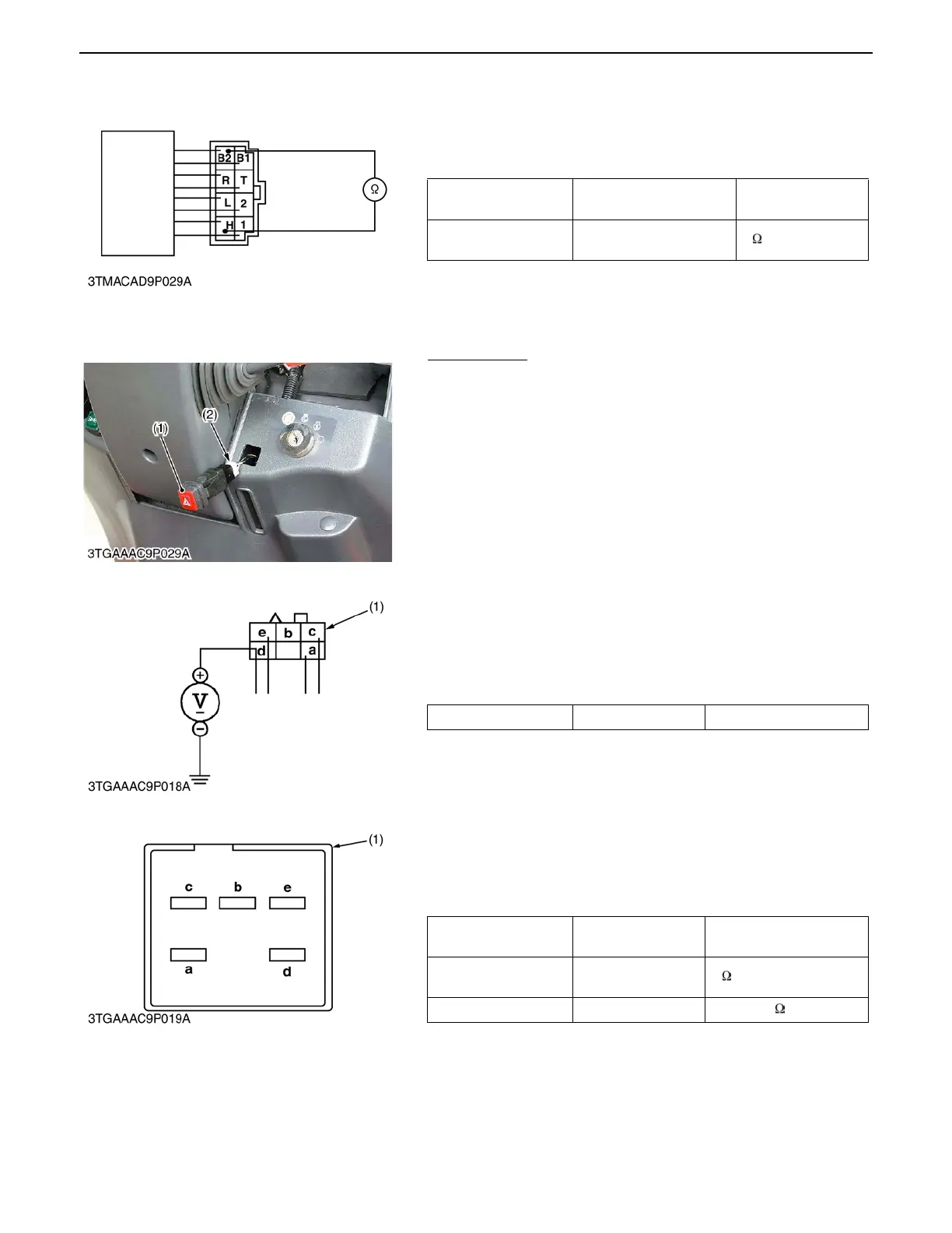
8) Horn Switch Continuity
1. Measure the resistance with an ohmmeter across the B2
terminal to the H terminal.
2. If measurement is not following below, the horn switch is
faulty.
(16)Hazard Switch
Hazard Switch
1. Remove the meter panel and disconnect the 6P connector (2)
from hazard switch (1) after disconnect the battery negative
code.
2. Remove the hazard switch (1).
3. Perform the following checking.
1) Connector Voltage
1. Connect the battery negative code, and turn on the light
switch, then measure the voltage with a voltmeter across the
d terminal and chassis.
2. If the voltage differ from the battery voltage, the wiring harness
is faulty.
2) Hazard Switch Continuity
1. Measure the resistance with ohmmeter across the a terminal
and c terminal, and across the d terminal and e terminal.
2. If the measurement is not following below, the hazard switch
or the bulb are faulty.
Resistance
(Switch at OFF)
B2 terminal - T terminal Infinity
Resistance
(Switch at ON)
B2 terminal - 2 terminal 0
0000001782E
(1) Hazard Switch (2) 6P Connector
0000001783E
Voltage d terminal - Chassis Approx. battery voltage
(1) 6P Connector
0000007942E
Resistance
(Switch at OFF)
a terminal - c terminal Infinity
Resistance
(Switch at ON)
a terminal - c terminal 0
Resistance (Bulb) d terminal - e terminal Approx. 50
(1) Hazard Switch
0000007943E
 Loading...

