STV32 · STV36 · STV40, WSM TRANSMISSION
3-M3
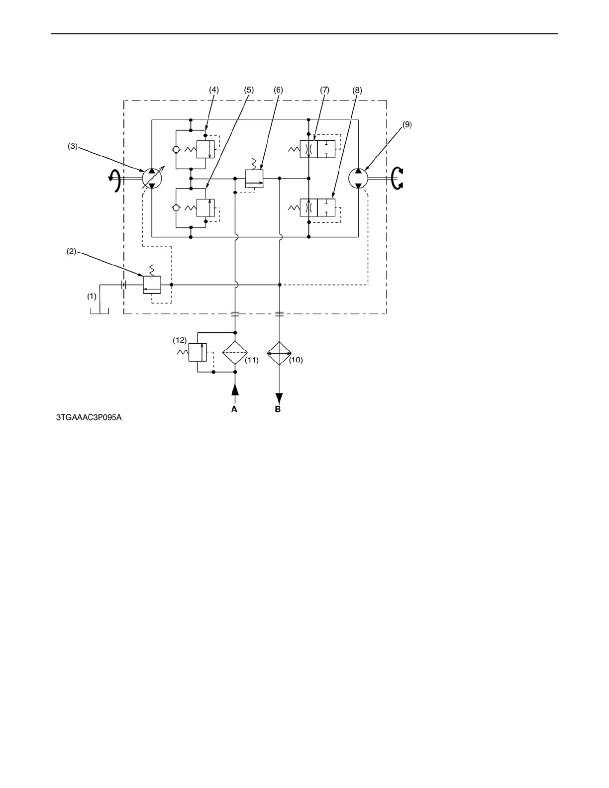
(2) Hydraulic Circuit
The HST pump is driven by the engine output power through the clutch and the drive shaft. The oil flow volume
and its direction is controlled by operating the speed change pedal or the cruise control lever, then the output speed
and direction of the HST motor is controlled.
The HST is structured the variable displacement pump, fixed displacement motor, oil filter, charge relief valve,
neutral valve, case relief valve etc.. The oil cooler is equipped on the drain circuit.
(1) Oil Tank (Transmission
Case)
(2) Case Relief Valve
(3) Variable Displacement
Pump (HST Pump)
(4) Check and High Pressure
Relief Valve (Forward)
(5) Check and High Pressure
Relief Valve (Reverse)
(6) Charge Relief Valve
(7) Neutral Valve (Forward)
(8) Neutral Valve (Reverse)
(9) Fixed Displacement
Motor (HST Motor)
(10) Oil Cooler
(11) Oil Filter
(12) Bypath Valve
A : From Power Steering
Controller
B : To Hydraulic Pump
0000007747E
 Loading...

