STV32 · STV36 · STV40, WSM HYDRAULIC SYSTEM
8-M13
[4] RELIEF VALVE
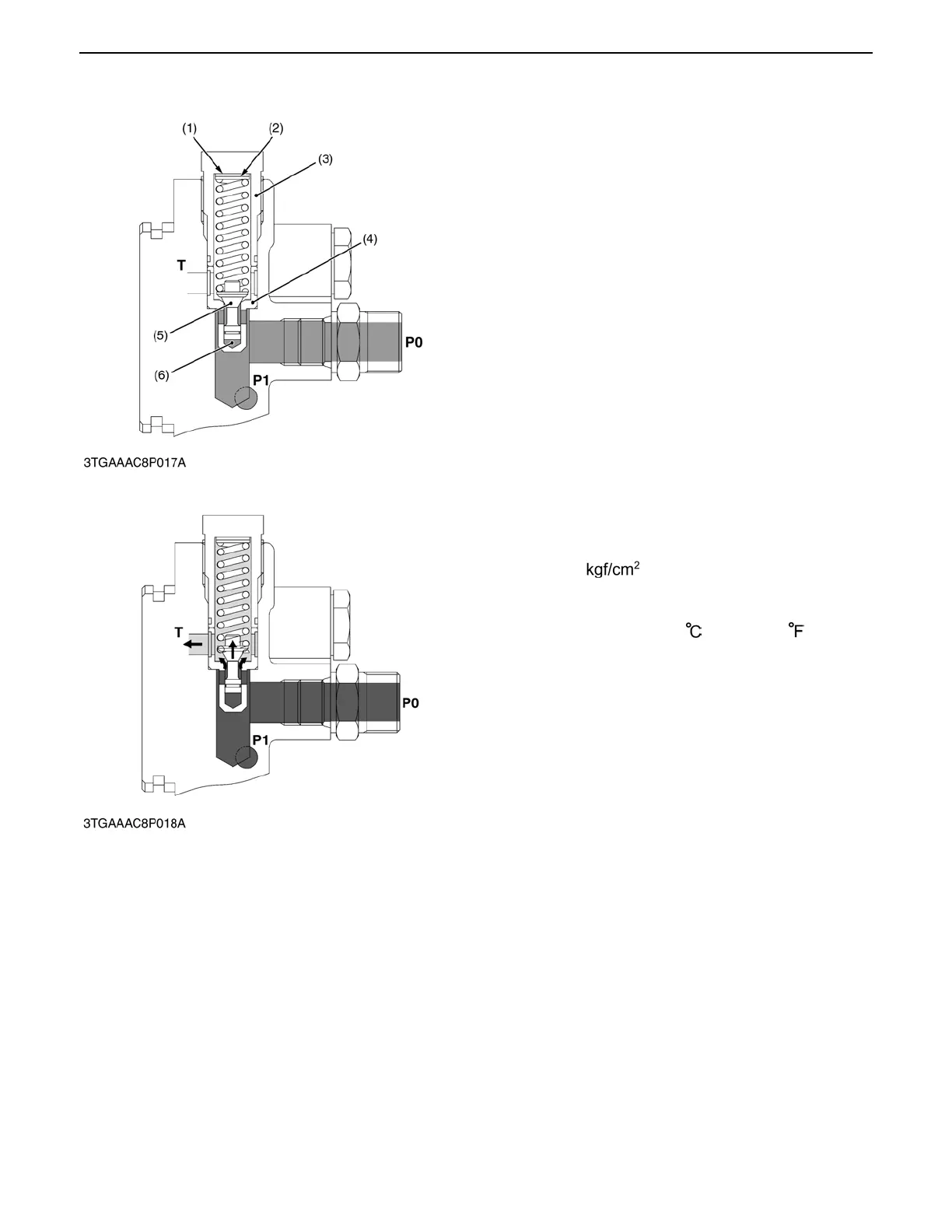
The 3-point hydraulic circuit has a relief valve to
restrict the maximum pressure in its circuit.
This is a guide piston relief valve with damper, a direct
acting relief valve suitable for relatively high pressure
and capacity, and constructed so as to prevent
chattering and other unstableness associated with
direct acting relief valves. As shown in the diagram,
poppet (5) has a guide, and there is a valve chamber
called a damping chamber (6) in the base of this guide
piston. The valve inlet is connected to this chamber
through the clearance between the guide surface and
the seat so that the chamber provides a damping effect,
controlling valve vibration.
When the pressure in the circuit rises, the pressure in
the damping chamber also rises, and when it exceeds
the relief pressure setting the spring is compressed,
making a clearance between the poppet and the seat.
The hydraulic oil can escape to the transmission case
through this clearance, controlling the pressure rise.
(Reference)
A Relief valve setting pressure
16.7 to 17.2 MPa
170 to 175
2417.4 to 2488.5 psi
Engine speed: Maximum
Oil temperature: 40 to 60 (104 to 140 )
(1) Washer T : Tank Port
(2) Shim P0 : P0 Port (Pump Port)
(3) Plug P1 : P1 Port (To Auxiliary
(4) Seat Control Valve)
(5) Poppet
(6) Damping Chamber
0000007837E
 Loading...

