STV32 · STV36 · STV40, WSM ELECTRICAL SYSTEM
9-M8
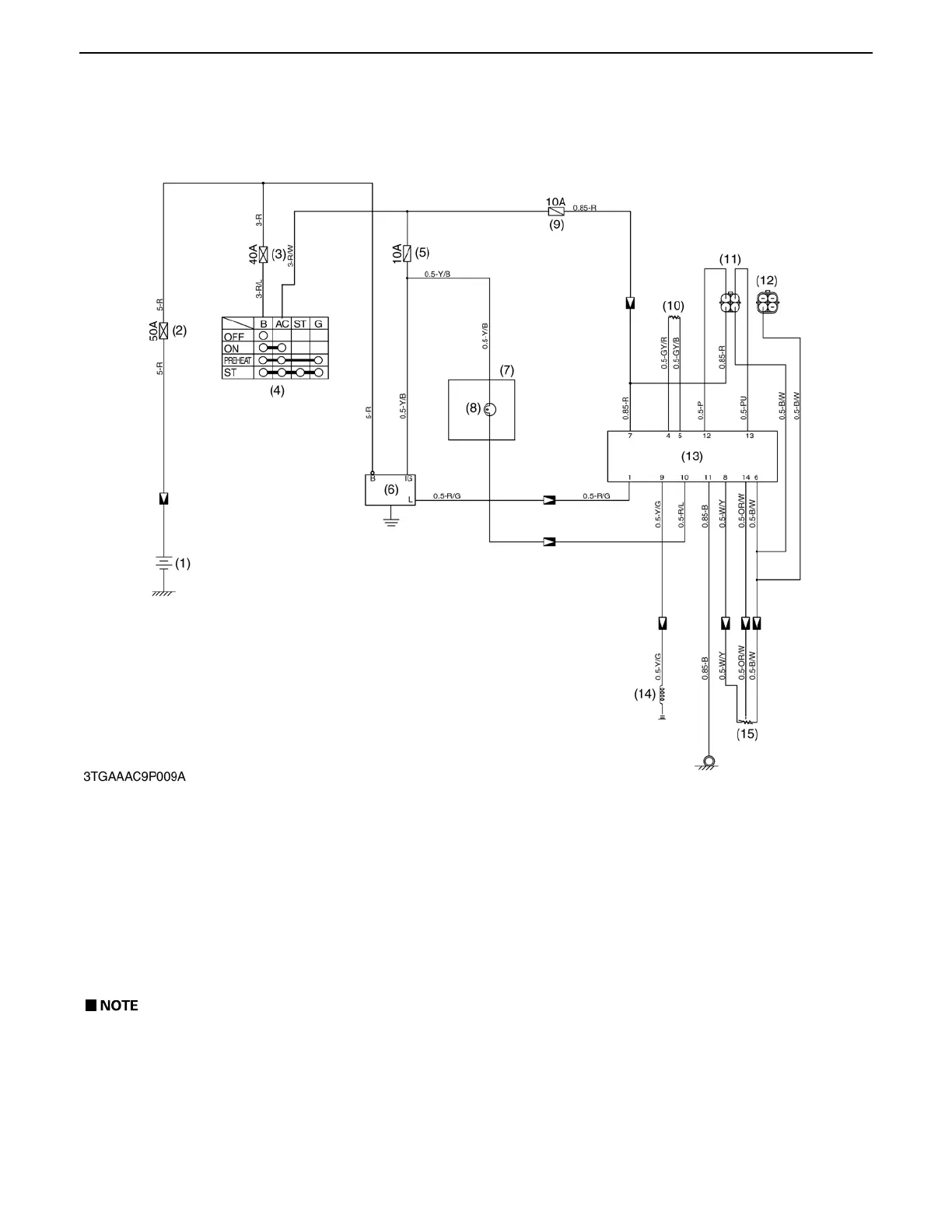
5. BI-SPEED TURN SYSTEM
[1] ELECTRICAL CIRCUIT
The bi-speed turn system is composed of traveling speed sensor, front wheel turning angle sensor, bi-speed switch,
engine running sensor (Alternator L terminal) and bi-speed valve. Those are controlled by bi-speed controller.
This system equipped with fail safe system. If the electrical sensor (Bi-speed valve, front wheel turning angle
sensor or traveling speed sensor) has failed, the bi-speed indicator lamp that located on the instrument panel will flash
on to mention the system failure. (Refer to 9-S9.)
(1) Battery (5) Fuse (Panel Board) (9) Fuse (Control Box) (13) Bi-speed Control Box
(2) Fuse (Main) (6) Alternator (10) Speed Sensor (14) Bi-speed Solenoid
(3) Fuse (Main Switch) (7) Instrument Panel (11) Checking Connector (15) Turning Angle Sensor
(4) Main Switch (8) Bi-speed Turn Indicator (12) Cap
A Bi-speed turn system is also explained in 3. TRANSMISSION, refer to 3-M15.
0000007893E
 Loading...

