STV32 · STV36 · STV40, WSM TRANSMISSION
3-M13
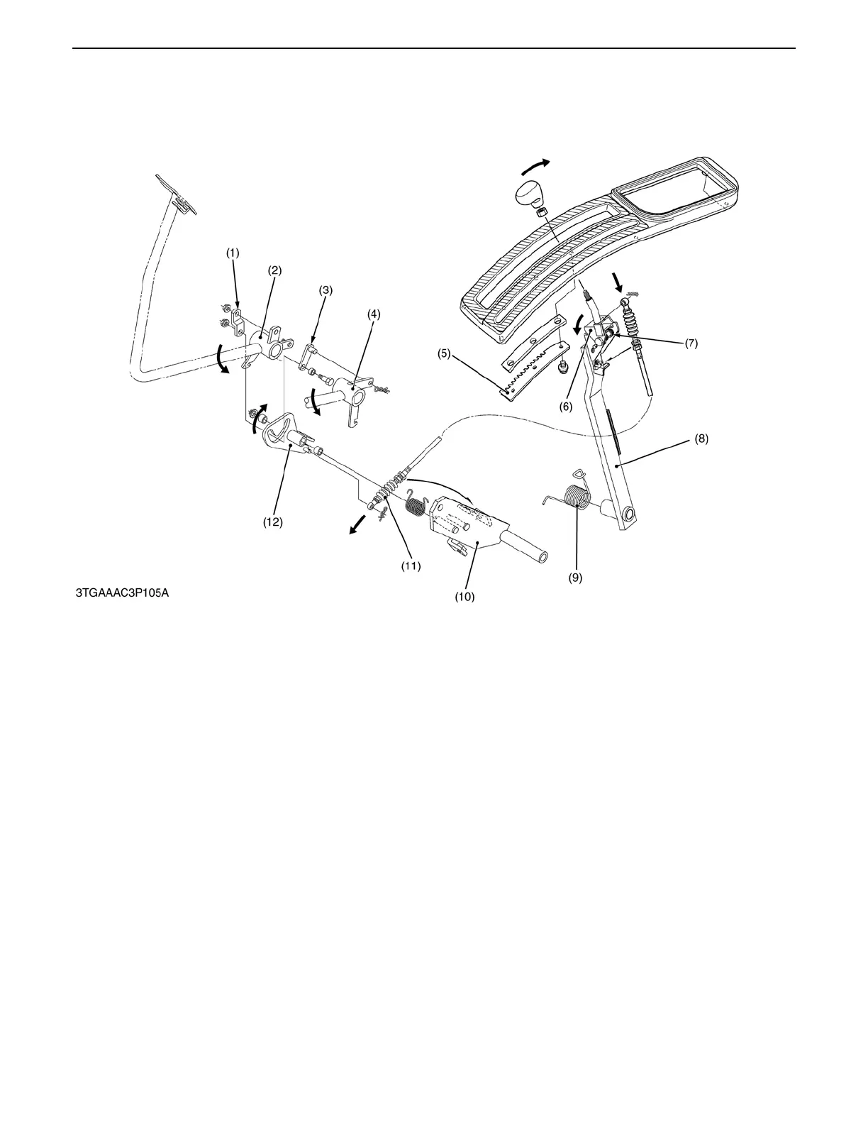
(7) Cruise Control Release System
The claw portion of the release lever (6) engages with the lever guide (5) by the spring (7) when the cruise control
lever is set.
When the right and left brake pedal (2) (4) is depressed at the same time, the lever 1 (12) rotates in the direction
of the arrow of figure by the brake link 1 (1) and 2 (3). Then, the inner wire of release wire (11) is pulled, and release
lever (6) rotates in the direction of the arrow of figure. The claw portion of the release lever (6) comes off from lever
guide (5), and after all, the cruise control lever (8) returns to home position by spring (9).
When one of the brake pedal is depressed, the brake link 1 (1) and 2 (3) move along the ditch part of the lever (12),
and the lever 1 (12) does not rotate.
(1) Brake Link 1 (4) Brake Pedal LH (7) Spring (10) HST Pedal Support
(2) Brake Pedal RH (5) Lever Guide (8) Cruise Control Lever (11) Release Wire
(3) Brake Link 2 (6) Release Lever Assembly (12) Lever 1
(9) Spring
0000007762E
 Loading...

